Difference between revisions of "Support book"
| (5 intermediate revisions by 2 users not shown) | |||
| Line 1: | Line 1: | ||
| − | {{DISPLAYTITLE: VoIP Switch | + | {{DISPLAYTITLE: Book VoIP Switch Support }} |
{{PAGE_HEADER}} | {{PAGE_HEADER}} | ||
| − | {{ | + | {{Page_Menu_List_Help_Support}} |
<!-- FOOTER LEFT "© Aarenet AG 2017" --> <!-- PDF Creation Directive ------------------------------> | <!-- FOOTER LEFT "© Aarenet AG 2017" --> <!-- PDF Creation Directive ------------------------------> | ||
| − | |||
| − | [[File:an_its_know_how. | + | [[File:an_its_know_how.jpg|link=|It's not magic it's know how]] <!--|14px --> |
| Line 12: | Line 11: | ||
{{Page_Introduction_Title}} | {{Page_Introduction_Title}} | ||
<!-- Transclusion : Intro Begin ------------------------------------------------------------------><section begin=intro /> | <!-- Transclusion : Intro Begin ------------------------------------------------------------------><section begin=intro /> | ||
| − | The | + | The Aarenet VoIP System supporting personnel find here links to detailed information about: |
| − | :* | + | :* How to support telephony users and solving user problems |
| − | + | :* An introduction to the VoIP signaling protocols | |
| + | :* The Aarenet VoIP Switch on board support tools | ||
| + | :* The Aarenet VoIP System monitoring and alarming | ||
| + | :* The maintenance and problem solving of the Aarenet VoIP Switch | ||
| + | :* The maintenance and problem solving of DELL server | ||
<!-- Transclusion : Intro End --------------------------------------------------------------------><section end=intro /> | <!-- Transclusion : Intro End --------------------------------------------------------------------><section end=intro /> | ||
| − | + | __NOTOC__ <!-- Table of Contents --------------------------------------------------------------------> | |
<!-- =========================================================================================== --> | <!-- =========================================================================================== --> | ||
| + | <!-- Transclusion : Article Begin -----------------------------------------------------------------><section begin=article /> | ||
<!-- PAGE BREAK --> <!-- PDF Creation Directive ---------------------------------------------------> | <!-- PAGE BREAK --> <!-- PDF Creation Directive ---------------------------------------------------> | ||
| − | = | + | = User Guide for Solving Telephony Problems (Support Level 1) = |
| − | {{PAGE_SECTION_TRANSCLUDE | link={{NAMESPACE}}: | + | {{PAGE_SECTION_TRANSCLUDE | link={{NAMESPACE}}:user_support_level1 }} <!-- {{#lst:{{NAMESPACE}}:user_support_level1 | article }} --> |
| Line 32: | Line 36: | ||
<!-- =========================================================================================== --> | <!-- =========================================================================================== --> | ||
<!-- PAGE BREAK --> <!-- PDF Creation Directive ---------------------------------------------------> | <!-- PAGE BREAK --> <!-- PDF Creation Directive ---------------------------------------------------> | ||
| − | = | + | = Introduction for Supporting User Problems (Support Level 2) = |
| + | |||
| + | {{PAGE_SECTION_TRANSCLUDE | link={{NAMESPACE}}:support_user_level2 }} <!-- {{#lst:{{NAMESPACE}}:support_user_level2 | article }} --> | ||
| + | |||
| + | |||
| − | + | ||
| + | <!-- =========================================================================================== --> | ||
<!-- PAGE BREAK --> <!-- PDF Creation Directive ---------------------------------------------------> | <!-- PAGE BREAK --> <!-- PDF Creation Directive ---------------------------------------------------> | ||
| − | {{PAGE_SECTION_TRANSCLUDE | link={{NAMESPACE}}: | + | = Manual of the Aarenet VoIP Switch Support Tools = |
| + | |||
| + | {{PAGE_SECTION_TRANSCLUDE | link={{NAMESPACE}}:support_tools }} <!-- {{#lst:{{NAMESPACE}}:support_tools | article }} --> | ||
| + | |||
| + | |||
| + | {{#ifeq: {{An_Wiki_Site}} | test_wiki | | ||
| + | |||
| + | <!-- =========================================================================================== --> | ||
<!-- PAGE BREAK --> <!-- PDF Creation Directive ---------------------------------------------------> | <!-- PAGE BREAK --> <!-- PDF Creation Directive ---------------------------------------------------> | ||
| − | {{PAGE_SECTION_TRANSCLUDE | link={{NAMESPACE}}: | + | = Tutorial for Aarenet VoIP System Monitoring and Alarming {{Help_Status || comingsoon }} = |
| + | |||
| + | {{PAGE_SECTION_TRANSCLUDE | link={{NAMESPACE}}:support_monitoring }} <!-- {{#lst:{{NAMESPACE}}:support_monitoring | article }} --> | ||
| + | |||
| + | }} | ||
| + | |||
| + | |||
| + | <!-- =========================================================================================== --> | ||
<!-- PAGE BREAK --> <!-- PDF Creation Directive ---------------------------------------------------> | <!-- PAGE BREAK --> <!-- PDF Creation Directive ---------------------------------------------------> | ||
| − | {{PAGE_SECTION_TRANSCLUDE | link={{NAMESPACE}}: | + | = Manual for the Maintenance and Problem Solving of the Aarenet VoIP Switch = |
| + | |||
| + | {{PAGE_SECTION_TRANSCLUDE | link={{NAMESPACE}}:support_switch }} <!-- {{#lst:{{NAMESPACE}}:support_switch | article }} --> | ||
| + | |||
| + | |||
| + | |||
| + | |||
| + | <!-- =========================================================================================== --> | ||
<!-- PAGE BREAK --> <!-- PDF Creation Directive ---------------------------------------------------> | <!-- PAGE BREAK --> <!-- PDF Creation Directive ---------------------------------------------------> | ||
| − | + | = Guide for the Maintenance and Problem Solving for Servers from DELL Inc ® = | |
| − | + | ||
| − | + | {{PAGE_SECTION_TRANSCLUDE | link={{NAMESPACE}}:support_server_dell }} <!-- {{#lst:{{NAMESPACE}}:support_server_dell | article }} --> | |
| − | |||
| − | {{PAGE_SECTION_TRANSCLUDE | link={{NAMESPACE}}: | ||
| − | |||
| − | |||
| − | |||
| − | |||
| − | |||
| − | |||
| − | |||
| − | |||
| Line 61: | Line 81: | ||
<!-- =========================================================================================== --> | <!-- =========================================================================================== --> | ||
<!-- PAGE BREAK --> <!-- PDF Creation Directive ---------------------------------------------------> | <!-- PAGE BREAK --> <!-- PDF Creation Directive ---------------------------------------------------> | ||
| − | = | + | = Brief Tutorial of the SIP Signaling and SDP Media Protocols = |
| − | {{PAGE_SECTION_TRANSCLUDE | link={{NAMESPACE}}: | + | {{PAGE_SECTION_TRANSCLUDE | link={{NAMESPACE}}:support_voip_protocol }} <!-- {{#lst:{{NAMESPACE}}:support_voip_protocol | article }} --> |
| − | <!-- | ||
| − | {{ | ||
| − | |||
| − | |||
| − | |||
| − | |||
| − | |||
| − | |||
| − | |||
| − | |||
| − | |||
| − | |||
| − | |||
| − | |||
Latest revision as of 14:30, 5 September 2017
| Note | The features and/or parameters listed in this article may not be available from your telephone service provider. |
|
|
|
|
|

Introduction
The Aarenet VoIP System supporting personnel find here links to detailed information about:
- How to support telephony users and solving user problems
- An introduction to the VoIP signaling protocols
- The Aarenet VoIP Switch on board support tools
- The Aarenet VoIP System monitoring and alarming
- The maintenance and problem solving of the Aarenet VoIP Switch
- The maintenance and problem solving of DELL server
User Guide for Solving Telephony Problems (Support Level 1)
Best Practice: How do I start to solve my problem?
| Best Practice |
|
Basic Check of the VoIP Device
The following basic conditions must always be checked first:
- Is the VoIP terminal correctly connected to the power supply?
- → Possible actions:
- Replace the power supply cable
- Use a different outlet
- → Possible actions:
- Is the VoIP terminal correctly connected to the data network?
- Plug the data cable into the correct port:
- At the VoIP device
- At the upstream IP device (IP router, xDLS modem, etc.)
- → Possible actions:
- Replace the data cable
- Does the VoIP device display the behavior and indicators described in its user manual?
- If it's not:
- → Possible actions:
- Contact the seller's or device manufacturer's support
- Does your data network connection work?
- If your Internet connection for your PC and the VoIP device is running via the same upstream device (xDSL modem, FTTH modem (fibre optic modem), cable modem), can the Internet be accessed via your PC?
- I don't know or if no:
- → Possible actions:
- Contact the support of the Internet provider
| Warning |
|
The VoIP Device doesn't load the Configuration from the VoIP Switch
| Note |
These instructions are only valid if:
|
How does the problem manifest itself:
You are trying to use the VoIP device for the first time or after a restart of the device with the default factory configuration, but:
- Nothing's working!
Verify in the user account of the self-care GUI:
-
 Tab "Phones"
 - Click on the Button [ State... ]
- The "Last Access" parameter does not display the date/time and IP address of the VoIP device.
- The "MAC provisioning" parameter does not display "done".
Check the following conditions and take action:
- Are the basic conditions fulfilled?
- Is the VoIP device getting an IP address after connecting to the network?
- → Possible actions:
- Check network connection
- Check DHCP service in your local IP network
- → Possible actions:
- Is the web based user interface of the VoIP device accessible and can you log in?
- → Possible actions:
- Check network connection
- If the DHCP service is switched on in your local IP network, check via the telephone user or console interface whether the VoIP device obtains its IP address via DHCP.
- → Possible actions:
- Is the configuration of the VoIP terminal in factory defaults?
- If no:
- → Possible actions:
- Restart the device manually with the default factory configuration (see the user manual of the VoIP device)
- → Possible actions:
- Is the VoIP Switch available?
- or is the redirection server of the device manufacturer configured correctly?
- or is the redirection server of the device manufacturer reachable?
- → Possible actions:
- Contact the support of the telephony provider
If the problem cannot be solved, contact the provider's support with the following information:
- Telephone number of the device which causes problems
- Device type
- Date and time when the problem occurred
- Description of the problem:
- "The VoIP device cannot load its configuration!"
The VoIP Device doesn't Register with the VoIP Switch
| Note |
These instructions are only valid if:
|
How does the problem manifest itself:
The telephone (VoIP device) is used for the first time or it has already been possible to make a phone call (incoming and outgoing), but:
- Neither an incoming nor outgoing connection can be established with the VoIP device.
- An outgoing connection can be established with the VoIP terminal, but it is not possible to reach it inbound.
Verify in the user account of the self-care GUI:
-
 Tab "Phones"
 - Click on the Button [ State... ]
- At "Registrations" no user agent, no IP address, no contact is displayed.
Check the following conditions and take action:
- Are the basic conditions fulfilled?
- Did the VoIP device load the configuration?
- If no:
- → Possible actions:
- Configure the device manually or via the VoIP Switch.
- → Possible actions:
- What does the log of the VoIP device show?
- → Possible actions
- Act according to the instructions of the VoIP device.
If the problem cannot be solved, contact the provider's support with the following information:
- Telephone number of the device which causes problems
- Device type
- Date and time when the problem occurred
- Description of the problem:
- "The VoIP device cannot register!"
The VoIP Device cannot Establish or Receive Connections
How does the problem manifest itself:
The telephone (VoIP terminal) has already been able to make (incoming and outgoing) calls, but now:
- The VoIP device cannot establish or receive connections to/from public or private vPBX phone numbers whose devices are verifiably working (e. g. checked with an mobile phone).
Check the following conditions and take action:
- Are the basic conditions fulfilled?
- Has this VoIP device registered?
- → Possible actions:
- Check if the device is registered on the VoIP Switch .
- → Possible actions:
- For problems with incoming connections:
- Is a call forwarding active?
- → Possible actions:
- Check with *#00 if a call forwarding is configured and deactivate with *00 if necessary.
- If your VoIP device has a private vPBX phone number, have the vPBX administrator check if the call distribution is still working correctly.
- For problems with outgoing connections:
- Check with another device, e.g. a mobile phone or other phone of the same vPBX, if the desired destination number is reachable.
- If no:
- → Possible actions:
- If you have a public phone number:
- Check if a TopStop has been exceeded?
- Is the desired destination number blocked by a RuleSet?
- Contact the support of the telephony provider
-
- If you have a private vPBX number:
- Check if you need a leading 0, an other digit or no digit for outgoing calls to the PSTN.
- Check if a TopStop has been exceeded?
- Is the desired destination number blocked by a RuleSet?
- Contact the vPBX administrator
- → Possible actions:
If the problem cannot be solved, contact the provider's support with the following information:
- Telephone number of the device which causes problems
- Date and time when the problem occurred
- Telephone numbers of the participating devices:
- A Number of the calling side
- B Number of the called side
- Description of the problem:
- "A cannot make calls"
- "A cannot receive calls"
- "A cannot make calls to certain B numbers:"
- List of B numbers that cannot be called
Poor, Partly or Completely Missing Speech Transmission
How does the problem manifest itself:
The VoIP device can establish or receive connections. The voice transmission was fine on earlier connections, but not now.
- The voice transmission is disturbed:
- B hears A disturbed
- A hears B disturbed
- The speech transmission is disturbed in both directions A <-> B
- The voice transmission is missing in part or in full since beginning of the connection:
- B does not hear A
- A does not hear B
- A and B do not hear each other
Check the following conditions and take action:
- Are the basic conditions fulfilled?
- Is the handset or headset connected correctly?
- Is the microphone of the handset or headset not muted?
- Are the volume levels for the loudspeaker and microphone on your telephone set correctly?
- Is the problem only with a specific parter? If yes, the other party should check the volume of the microphones, headset and headset being used.
- Remember:
- Handsfree mode often produces poor voice quality.
- Connections with mobile phones can be disrupted, especially when the call partner is traveling.
If the problem cannot be solved, contact the provider's support with the following information:
- Telephone number of the device which causes problems
- Date and time when the problem occurred
- Telephone numbers of the participating devices:
- A Number of the calling side
- B Number of the called side
- Description of the problem:
- "The voice transmission is disturbed:"
- B hears A disturbed
- A hears B disturbed
- The speech transmission is disturbed in both directions A <-> B
- "The voice transmission is missing in part or in full since beginning of the connection:"
- B does not hear A
- A does not hear B
- A and B do not hear each other
FAX Transmissions do not or Only Partially Work
In a VoIP environment FAX no longer achieve the same degree of reliability as before in an analogue or ISDN one. The FAX reliability depends on various factors such as the type of device, device settings and the way the device is connected to the IP network. It depends also on the quality of the transmitter and receiver of the peer FAX devices. Getting all these factors together a transmission may not even start or dropped unexpectedly. The transmitted documents may be incomplete.
The users must expect increasing difficulties in the future, especially for international transmissions.
How does the problem manifest itself:
- FAX transmission doesn't start
- FAX transmission is dropped
- The transmitted document is incomplete
Check the following conditions and take action:
- Adjust the FAX device configuration:
- Reduce the transmission speed to max. 9600bds.
- Switch OFF the error correction, e.g. EMC
- If the device offers a "VoIP mode" then experiment with it and check if the results are better.
If the problem cannot be solved, contact the provider's support with the following information:
- Telephone number of the device which causes problems
- Device type
- Date and time when the problem occurred
- Telephone numbers of the participating devices:
- A Number of the calling side
- B Number of the called side
- Description of the problem:
- "FAX Transmissions doesn't work"
-
- → Don't expect miracles from the support!
Introduction for Supporting User Problems (Support Level 2)
Introduction Support Level 2
The level 2 support is the first instance where the user's telephony problems are handled that a user cannot solve himself. Additionally the level 2 supporter must be able to detect if the user problem is a "single" problem or if there is a large scale problem, that produces the same problem for multiple customers, e.g. data transfer problems in the Internet so that no VoIP call signaling is possible.
The level 2 supporter must be aware of the complexity of a VoIP system and the multitude of telephony solutions on the user side. Further he needs an understanding of:
- IP networking
- VoIP protocols SIP for signaling, SDP and RTP for speech transmission.
Overview of a VoIP system and the multitude of user telephony solutions:
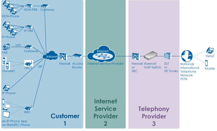
The level 2 supporter faces problems with the following layers:
- Equipment
- IP data transfer
- Telephony service
And each of this layer can be located into the following raw areas:
- Customer/User site
- Internet Service Provider ISP
- Telephony Provider
This layer and dividing into areas produces a "3x3 Support Matrix":
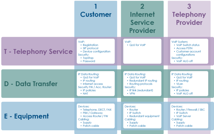
Within this "3x3 Support Matrix" the supporter can:
- advice the customer what to do when the problem is located in the nodes 1-T, 1-D and 1-E
- check the customer configurations on the VoIP Switch, node 3-T, and, if he has operator rights, adjust configurations.
For the other cases the level 2 supporter must be able to identify if:
- the user must contact his ISP, due to possible Internet access problems
- the VoIP System administrator must be involved, due to possible telephony service problems
- Hint:
- These cases indicate mostly large scale problems within the VoIP system!
Best Practice for Handling an User Problem
| Best Practice |
|
The supporter shall record the user information and the results of the own research:
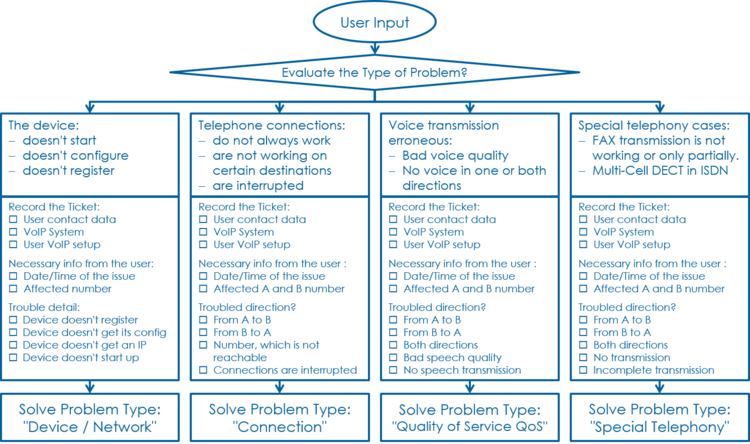
| Note |
This information is most welcome if the supporter needs the support of the provider and has to inform him about the case. |
Step 1: Record the Customer's Data and Problem Description
Get the Customer's Data
From the customer get:
- Name of the caller
- Telephone number of the caller
- if applicable the company name
Write down the Customer's Problem Description
From the customer get:
- Date and time of the issue
- The involved telephone numbers
- The problem description
If the customer doesn't know then identify via the ConfigCenter the telephone number and its associated account.
Step 2: Cross Check the User Inputs
With this cross check the supporter can validate the user information, gets an impression of the state of the account and will probably find the reason for the user problem...
Via ConfigCenter check the users status and account configuration on the VoIP Switch:
- Check "Validity":
- Check if the user account and its addresses are existing and "valid".
- Check the telephone number registration status.
- If there is no registration you can proceed directly with
 The user device is not registered ...
- If there is no registration you can proceed directly with
- Check "TopStop":
- Check if a TopStop in the account or address prevents the user from doing outgoing calls.
- Check "RuleSet":
- Check if a selected RuleSet in the account or address configuration prevents the user from doing outgoing or receiving calls.
- Check "Call Forwards" or "Call Rejecting":
- Check if a "Call Forwards" or "Call Rejecting" in the account prevents the user from doing outgoing or receiving calls.
- Check "Call Data":
- Consult the "Call Data" for the last connection attempts and connections longer than 2min of the user.
Step 3: Evaluate the User's VoIP Setup
For questioning and analyzing the user's problem it is necessary that the supporter is aware of the VoIP setup of the user.
The experienced supporter knows of the user's VoIP setup after the cross check . If not here the supporter finds the most implemented VoIP setup's.
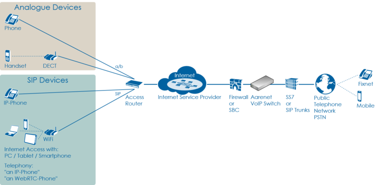
VoIP Setup: Residential
Characteristics:
- Private household
- Single or few telephone number
- Each telephone number registers individually
Most common problems:
- Account or telephone number blocked on the VoIP switch
- Telephone number not correctly ported to the telephony provider
- Telephone not correctly configured
- Telephone, cables defect
- Internet access fails
Overview VoIP Setup:
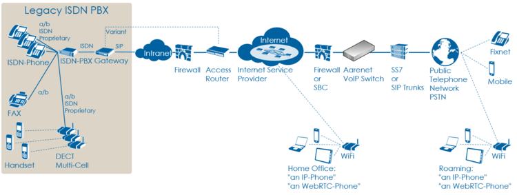
VoIP Setup: Legacy ISDN PBX
Characteristics:
- Company PBX
- The ISDN PBX is connected via BRI or PRI to an ISDN-SIP Gateway
- One or more telephone number ranges
- The telephone numbers are registered via a main number
- The telephone number of incoming calls are signaled with only a few digits
Most common problems:
- Account or telephone numbers blocked on the VoIP switch
- Telephone number ranges not correctly ported to the telephony provider
- Telephone number ranges not completely configured on the VoIP Switch
- Wrong incoming telephone number signaling
- Internet access fails
- The company Firewall VoIP ALG interferes with the SIP signaling or needed IP ports are blocked.
- QoS problems for speech, Fax, DECT
Overview VoIP Setup:
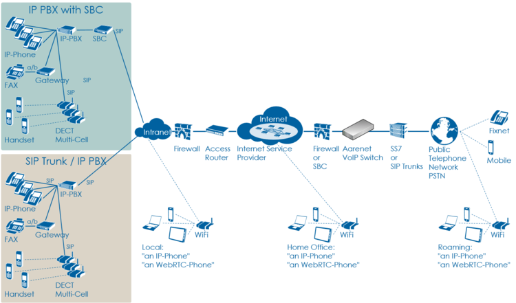
VoIP Setup: IP PBX
Characteristics:
- Company PBX
- The IP PBX is connected directly or via SBC to the VoIP Switch
- One or more telephone number ranges
- The telephone numbers are registered via a main number
Most common problems:
- Account or telephone numbers blocked on the VoIP switch
- Telephone number ranges not correctly ported to the telephony provider
- Telephone number ranges not completely configured on the VoIP Switch
- The company Firewall and/or SBC VoIP ALG interferes with the SIP signaling or needed IP ports are blocked.
- Internet access fails
- QoS problems for speech
Overview VoIP Setup:
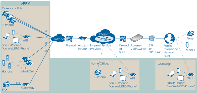
VoIP Setup: vPBX
Characteristics:
- Company PBX
- The IP Phones are connected directly to the VoIP Switch
- One or more telephone number ranges
Most common problems:
- Public account and/or public telephone numbers blocked on the VoIP switch
- Public telephone number ranges not correctly ported to the telephony provider
- Telephone number ranges not completely configured on the VoIP Switch
- Private account and/or private telephone numbers blocked on the VoIP switch
- Provisioning of the SIP devices out of the AdminCenter
- The company or home office Firewalls and/or SBCs VoIP policies or ALG interferes with the SIP signaling or needed IP ports are blocked.
- Company/home office Internet access fails
- QoS problems for speech, FAX, DECT
Overview VoIP Setup:
Step 4: Check the "Big Picture"
At this point the supporter should get aware if the problem is limited to this user or if it could be large scale problem within the VoIP System.
If the supporter suspects a large scale problem, due to a great amount of the same ore similar user complains then he should contact the telephony provider support or emergency organization.
If the supporter has enough privileges he can check:
- The VoIP Switch component status
- This will show if the VoIP Switch itself has a problem.
- The VoIP System monitor
- Here you can check if:
- The registrations dropped in a large scale
- The calls dropped in a large scale
- The IP connectivity somewhere in the VoIP system failed
- Here you can check if:
At any rate the supporter must inform the VoIP system administrator!
Step 5: Solve the Customer Problem
Solve "Device / Network / Configuration / Registration" Problems
This problem type covers the following erroneous conditions:
- The device doesn't start
- The device doesn't integrate into the IP network
- The device is not correctly configured
- The device doesn't register at the VoIP Switch
| Note |
If the device is connected to an IP-PBX then these problems must be solved with the responsible of the IP-PBX. |
Solve "Device Hardware & Firmware" Problem
1 Step: Is the device powered on, not defect?
| Customer | Internet ISP |
Telephony Provider | |
| Telephony | |||
| Data Transfer | |||
| Equipment | Check if the device correctly powered and shows basic activity?
Actions:
|
| Warning |
Defect power cables must be replaced! |
2 Step: Is the device connected to the IP network?
| Customer | Internet ISP |
Telephony Provider | |
| Telephony | |||
| Data Transfer | |||
| Equipment | Is the device correctly connected to the IP network?
Actions:
|
3 Step: Has the device a reasonable firmware loaded?
| Customer | Internet ISP |
Telephony Provider | |
| Telephony | |||
| Data Transfer | |||
| Equipment | Has the device a reasonable firmware loaded?
Actions:
|
Solve "Device Network" Problem
1 Step: Has the device an IP address and can access the Internet?
| Customer | Internet ISP |
Telephony Provider | |
| Telephony | |||
| Data Transfer | Has the device got an IP address?
Actions:
Actions:
|
||
| Equipment |
Solve "Registration" Problem
1 Step: Review the account and telephone number configuration
| Customer | Internet ISP |
Telephony Provider | |
| Telephony | Check via ConfigCenter:
Actions:
| ||
| Data Transfer | |||
| Equipment |
2 Step: Where REGISTER messages received from the device on the VoIP Switch?
| Customer | Internet ISP |
Telephony Provider | |
| Telephony | In the "Support Log" search for the device registration in the present and past time.
Actions:
| ||
| Data Transfer | |||
| Equipment |
Failed registrations due to disabled account or address:
|
2017-09-15-07:56:49.553 Registration failed, disabled account aan1-00093 tried to register number 0449980010 |
Actions:
- Check why the account is disabled and activate if allowed.
Failed registrations due to wrong SIP credentials:
|
2017-09-15-08:05:38.117 Registration failed, invalid credentials for account acc-01 |
Actions:
- The user must manually adjust the SIP credentials on the device
- The user must re-configure the device via AdminCenter
The device didn't refresh its registration:
|
2017-09-15-07:59:00.862 RegID989961 ended for 0987654321 ip=111.111.111.111:65398 ua=my-device v1.0 |
Actions:
- Order the user to check if the device is really on-line!
- Order the user to check if the device is defect? powered on? patch? IP address? → see below
For information a successful registration:
|
2017-09-15-07:59:30.383 RegID989965 started for 0987654321 ip=111.111.111.111:65398 ua=my-device v1.0 |
Hint:
The supporter might try to find REGISTER messages from the device in the "Trace" . This gives the certainty that the message was received by the VoIP switch. The supporter can filter for the telephone number.
If the IP address is needed then the customer must be able to tell or evaluate it, e.g.:
3 Step: Is the device correctly configured for registration??
| Customer | Internet ISP |
Telephony Provider | |
| Telephony | For a manually configured device, check that the device has the correct configuration for:
Actions:
Actions:
For a automatically via AdminCenter configured device check that:
Actions:
|
||
| Data Transfer | |||
| Equipment |
Solve "Connection" Problems
This problem type covers the following erroneous conditions:
- Incoming or outgoing calls are not working
- Wrong called number
- Call supervision
- User device not registered
- User device not correct configured
- SIP signaling in general
| Note |
If the device is connected to an IP-PBX then these problems must be solved with the responsible of the IP-PBX. |
1 Step: Review the account and telephone number configuration / registration?
| Customer | Internet ISP |
Telephony Provider | |
| Telephony | Do this check for the A and/or B telephone number if they are on-net numbers of the VoIP SWitch.
Check via ConfigCenter:
Actions:
| ||
| Data Transfer | |||
| Equipment |
Hint:
- If the device is not registered outgoing calls might be working but NO incoming call will work.
2 Step: Was the called number correctly transmitted to the peer?
| Customer | Internet ISP |
Telephony Provider | |
| Telephony | Check via ConfigCenter:
Actions:
| ||
| Data Transfer | |||
| Equipment |
3 Step: What is the reason of an interrupted connection?
| Customer | Internet ISP |
Telephony Provider | |
| Telephony | Search in the "Call Data" for the erroneous call:
Actions:
Actions:
Actions:
Actions: |
||
| Data Transfer | |||
| Equipment |
Solve "Quality of Service QoS" QoS-Problems
Introduction to QoS-Problems
| Note |
In most cases, QoS-problems can only be found and solved by means of an exclusion procedure.
|
The QoS-problem type covers the following erroneous conditions:
- No voice transmission in one or both directions from the beginning of the connection
- Bad voice quality during the connection
Naming and characteristics of QoS-problem:
- One/No-Way Connection:
- There is no speech transmission in one or both directions from beginning of the connection:
- Silence (Possible reason: Mostly due to no or blocked RTP data transmission)
- There is no speech transmission in one or both directions from beginning of the connection:
- Glitch Connection:
- There is speech transmission but it is disturbed:
- Crackle, clicking (Possible reason: small packet loss, jitter)
- Short interruption (Possible reason: bigger packet loss)
- Ouw-ing (Possible reason: jitter, transcoding)
- Echo (Possible reason: jitter, big delay)
- There is speech transmission but it is disturbed:
The source of the QoS-problems are all too often somewhere in the data transmission "D Data Transfer" layer (but sometimes they are surprisingly simple):
- The microphone or loadspeaker in the telephone handset defect
- Volume configuration in the telephone set wrong
- Telephone defect
- The company Intranet is not made ready for VoIP
- Any device in the "D - Data Transfer" layer
1st Step: Interview the User
1 Step: Interview the user carefully and identify the type of QoS-problem
Get all information from the user:
- Occurs the the QoS-problem with all peers or just with the given B peer?
- Hint:
- If the problem occurs only with the B peer then this is a strong indication that something is wrong on the B side!
- Is there no voice transmission, neither from A->B nor B->A?
- → Type of QoS-problem: "No-Way Connection"
- Is there voice transmission from A->B (B hears you) but none from B->A (you don't hear B)?
- → Type of QoS-problem: "One-Way Connection A->B"
- Is there voice transmission from B->A (you hear B) but none from A->B (B doesn't hear you)?
- → Type of QoS-problem: "One-Way Connection B->A"
- Are there during the connection crackle, clicking, short interruptions, uow-ing in the voice transmission for both sides?
- → Type of QoS-problem: "Glitch Connection"
- Are there during the connection crackle, clicking, short interruptions, uow-ing in the voice transmission from A->B?
- → Type of QoS-problem: "Glitch Connection A->B"
- Are there during the connection crackle, clicking, short interruptions, uow-ing in the voice transmission from B->A?
- → Type of QoS-problem: "Glitch Connection B->A"
- Uses the user an ISDN or DECT telephone behind an ISDN-PBX? Does the user have sharp clicking glitches in a regular or irregular interval? Do experience all users behind this ISDN-PBX this clicking?
- Remember :
- This points to a synchronization problem of the ISDN-PBX!
- Is one peer A or B a mobile user?
- Remember:
- Mobile networks often have QoS-problems on the wireless links between the base station and the mobile device!
Action:
- → Cross check the users information by checking the media transfer statistics of the affected connection, see "2 Step" below!
2nd Step: Localize the QoS-Problem
| Note |
It is very important that the supporter is aware of of the localization of the problem.
|
1 Step: Check the "Big Picture"
| Customer | Internet ISP |
Telephony Provider | |
| Telephony | |||
| Data Transfer | Check with the ISP where the user is connected to if there are outages in:
Actions:
|
Check with the ISP where the VoIP System is connected to if there are outages in:
Actions:
|
Check with the IT responsible of the IP network where the VoIP System is attached to:
Actions:
|
| Equipment |
2 Step: Identify the disturbed transmission direction from the VoIP Switch's view
This identification bases upon the VoIP System setting that all media streams are routed via the MediaServer of the VoIP Switch. The MediaServer collects statistic information about all media stream that are routed through it. These statistics can help to identify the source of the QoS-problem.
Search in the "Call Data" the CDR of the erroneous call:
- Set the "Call Data" filters:
- Insert at "Time" a reasonable time span where the erroneous call is to be expected.
- Set "Duration" to 00:00:00
- Insert at "Called Number" the called number
- Start the search and identify the CDR of the erroneous call in the list
- → If no CDR was found search for the "Calling Number"!
- Open the identified CDR
- Get the RTP statistics of this connection, click Button [ Media Trace ]
- If there are no data in the "Media Trace" contained then the media stream is not routed via the MediaServer of the VoIP Switch. See below how to force the routing via the MediaServer.
- Depending of the identified QoS-problem type analyze the RTP statistics detail, see below
If the media stream are not routed by default via MediaServer the supporter can force it for an account via the ConfigCenter:
-
 Menu "Account"
-
 Select the customers account
-
-
 Tab "Advanced"
-
-
 Set "Use always MediaServer" to "Yes"
-
| Note |
|
Localize "No-Way Connection" and Possible Actions
"No-Way Connection":
- No voice transmission, neither from A->B nor B->A
Knowhow background:
- May occur during commissioning of the customer connection for VoIP
- May occur when the telephony provider introduce now IP networks for new telephony users
- May occur when the Internet service provider or telephony provider modify the IP routing
- Customer firewall policies block IP range or UDP port range
- The peer devices negotiate not the same codec
- May occur when IP devices are defect
- User device defect
| Customer | Internet ISP |
Telephony Provider | |
| Telephony | |||
| Data Transfer | Assumption: The problem reporting user/customer shall be the A leg.
3rd: Check the "rtp data" records if the RTP transfer from and to the user/customer is not working:
| ||
| Equipment |
Localize "One-Way Connection A->B" and Possible Actions
"One-Way Connection A->B":
- B hears A but A doesn't hear B
Knowhow background:
- May occur during commissioning of the customer connection for VoIP
- May occur when the telephony provider introduce now IP networks for new telephony users
- May occur when the Internet service provider or telephony provider modify the IP routing
- Customer firewall policies block IP range or UDP port range
- The peer devices negotiate not the same codec
- May occur when IP devices are defect
- User device defect
| Customer | Internet ISP |
Telephony Provider | |
| Telephony | |||
| Data Transfer | Assumption: The problem reporting user/customer shall be the A leg.
1st: Check if the negotiated "codec" are correct for both peers.
3rd: Check the "rtp data" records if the RTP transfer from the PSTN is not working:
| ||
| Equipment |
Localize "One-Way Connection B->A" and Possible Actions
"One-Way Connection B->A":
- A hears B but B doesn't hear A
Knowhow background:
- May occur during commissioning of the customer connection for VoIP
- May occur when the telephony provider introduce now IP networks for new telephony users
- May occur when the Internet service provider or telephony provider modify the IP routing
- Customer firewall policies block IP range or UDP port range
- The peer devices negotiate not the same codec
- May occur when IP devices are defect
- User device defect
| Customer | Internet ISP |
Telephony Provider | |
| Telephony | |||
| Data Transfer | Assumption: The problem reporting user/customer shall be the A leg.
1st: Check if the negotiated "codec" are correct for both peers.
3rd: Check the "rtp data" records if the RTP transfer from the user is not working:
| ||
| Equipment |
Localize "Glitch Connection" and Possible Actions
"Glitch Connection":
- The voice transmission from A->B and B->A is disturbed
Knowhow background:
- May occur when the customers Intranet is not optimized for VoIP
- The peer devices negotiate not the same codec
- May occur when IP devices are defect
- User device defect
| Customer | Internet ISP |
Telephony Provider | |
| Telephony | |||
| Data Transfer | Assumption: The problem reporting user/customer shall be the A leg.
| ||
| Equipment |
Localize "Glitch Connection A->B" and Possible Actions
"Glitch Connection A->B":
- The voice transmission from A->B is disturbed. B claims to hear A with bad quality.
Knowhow background:
- May occur when the customers Intranet is not optimized for VoIP
- May occur when IP devices are defect
- User device defect
| Customer | Internet ISP |
Telephony Provider | |
| Telephony | |||
| Data Transfer | Assumption: The problem reporting user/customer shall be the A leg.
| ||
| Equipment |
Localize "Glitch Connection B->A" and Possible Actions
"Glitch Connection B->A":
- The voice transmission from B->A is disturbed. A claims to hear B with bad quality.
Knowhow background:
- May occur when the customers Intranet is not optimized for VoIP
- May occur when IP devices are defect
- User device defect
| Customer | Internet ISP |
Telephony Provider | |
| Telephony | |||
| Data Transfer | Assumption: The problem reporting user/customer shall be the A leg.
| ||
| Equipment |
Solve "Voice Glitches with ISDN-PBX" Problem
This problem type covers the following erroneous conditions:
- Bad speech quality in an ISDN-PBX environment
- Glitches in the voice transmission, it "clicks"
ISDN-PBX environment usually provide an excellent voice quality. In an VoIP environment this excellent voice quality can be only maintained if the ISDN-PBX can synchronize with high precision clock source.
1 Step: Check the ISDN reference clock
| Customer | Internet ISP |
Telephony Provider | |
| Telephony | |||
| Data Transfer | |||
| Equipment | Checks:
Actions:
|
Solve "Special Telephony" Problem
Solve "FAX Transmission" Problem
This problem type covers the following erroneous conditions:
- FAX transmission doesn't start
- FAX transmission is dropped
- The transmitted document is incomplete
| Note |
If the FAX is connected to an IP-PBX then FAX problems must be solved with the responsible of the IP-PBX. |
In a VoIP environment FAX no longer achieve the same degree of reliability as before in an analogue or ISDN one. The FAX reliability depends on various factors such as the type of device, device settings and the way the device is connected to the IP network. It depends also on the quality of the transmitter and receiver of the peer FAX devices. Getting all these factors together a transmission may not even start or dropped unexpectedly. The transmitted documents may be incomplete.
The users must expect increasing difficulties in the future, especially for international transmissions.
1 Step: Check the FAX device configuration
| Customer | Internet ISP |
Telephony Provider | |
| Telephony | |||
| Data Transfer | |||
| Equipment | Check:
Actions:
|
2 Step: Check the FAX transmission configuration of the gateway
| Customer | Internet ISP |
Telephony Provider | |
| Telephony | |||
| Data Transfer | |||
| Equipment | Depending on the quality of the IP network the supporter and/or administrator of the gateway can experiment with the FAX transmission protocol of the gateway device.
Checks:
Actions:
|
Solve "DECT Multi-Cell with ISDN-PBX" Problem
This problem type covers the following erroneous conditions:
- Hand over from cell to cell is not working
- Bad speech quality
| Note |
If the DECT Multi-Cell system is connected to an IP-PBX then DECT problems must be solved with the responsible of the IP-PBX. |
DECT-Multi-Cell systems connected to an ISDN-PBX which is working with in a VoIP environment experience special issues. Most issues are interconnected with accuracy of the synchronization clock of the ISDN-PBX. If this synchronization clock is not especially precise then the reference clock of the DECT-Multi-Cell system will have problems as described above.
1 Step: Check the ISDN reference clock
| Customer | Internet ISP |
Telephony Provider | |
| Telephony | |||
| Data Transfer | |||
| Equipment | Checks:
Actions:
|
Manual of the Aarenet VoIP Switch Support Tools
VoIP Switch ConfigCenter Support Tools
The ConfigCenter Support Log
The "Support Log" provides the supporter with information from the internal processes of the ServiceCenter:
- Registration
- Connection setup, release and exceptions
- Call Routing
- Used Ruleset
- Emergency calls
- etc
The "Support Log" provides filters for:
- Time based selection: From – Until, From – Duration
- Text filter
- Registration events
- Call events
- etc.
The "Support Log" has a limited history. The history may last from a few hours up to some days. The length of the history may be different from VoIP switch to VoIP switch and depends on the length of log files and amount of logging events.
| Note |
The "Support Log" is tenant sensitive. This means a supporter of tenant A is not able to see events of tenant B! |
ConfigCenter:
-
 Menu "Support"
-
 Menu "Support Log"
-
Get a "Support Log"
Dialog: "Support Log":
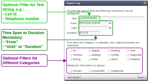
When the dialog "Support Log" opens it contains by default in "From" the actual date/time (-5min) and in "Duration" a duration of 5min:
- Click the Button [ Download ]
- Via HTTP an ASCII formatted file with the last 5 minutes will be downloaded
Retrieving a "Support Log" in the past:
- Insert the in "From" the desired start date/time
- Insert in "Duration" the needed length
- Press on the PC keyboard the 'Enter' key : The "Until" date/time will be computed
- Click the Button [ Download ]
or
- Insert the in "From" the desired start date/time
- Insert the in "Until" the desired stop date/time
- Press on the PC keyboard the 'Enter' key: The "Duration" will be computed
- Click the Button [ Download ]
| Best Practice |
Get the events of a connection in the past:
|
Interpretation of a "Support Log"
The interpretation of a "Support Log" is quite easy and straight forward. With a little experience one will be soon familiar with the interpretation.
Interpretation and example of a call setup and release:
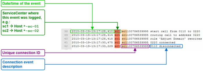
ConfigCenter Trace
The "Trace" provides the supporter with information from the message traffic between the VoIP switch and external VoIP devices, such as PSTN gateway, SIP CPE, SIP or MGCP telephones.
The "Trace" contains:
- Session Initiation Protocol SIP registration and connection signaling messages
- Media Gateway Control Protocol MGCP audit and endpoint control messages
- Session Description Protocol SDP streaming media initialization parameters
The "Trace" provides filters for:
- Time based selection: From – Until, From – Duration
- Text filter
The "Trace" has a limited history. The history may last from a few hours up to some days. The length of the history may be different from VoIP switch to VoIP switch and depends on the length of log files and amount of logging events.
The interpretation of a "Trace" (PCAP formatted file) has to be done in an external application like Wireshark network protocol analyzer. Wireshark offers deep and rich VoIP analysis .
| Note |
The "Trace" is not tenant sensitive. This means a supporter of tenant A is able to see signaling messages of tenant B! Due to this open display of information it may be possible that the "Trace" is not available for the supporters and operators on a multi tenant VoIP Switch. |
ConfigCenter:
-
 Menu "Support"
-
 Menu "Trace"
-
Get a "Trace"
Dialog: "Trace":
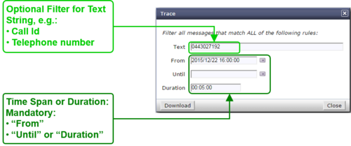
When the dialog "Trace" opens it contains by default in "From" the actual date/time (-5min) and in "Duration" a duration of 5min:
- Click the Button [ Download ]
- Via HTTP an PCAP formatted file with the last 5 minutes will be downloaded
Retrieving a "Trace" in the past:
- Insert the in "From" the desired start date/time
- Insert in "Duration" the needed length
- Press on the PC keyboard the 'Enter' key: The "Until" date/time will be computed
- Click the Button [ Download ]
or
- Insert the in "From" the desired start date/time
- Insert the in "Until" the desired stop date/time
- Press on the PC keyboard the 'Enter' key: The "Duration" will be computed
- Click the Button [ Download ]
| Best Practice |
Get the events of a connection in the past:
|
Interpretation of a "Trace"
The interpretation of a "Trace" needs experience!
For more information:
- See also article "Brief Tutorial of the SIP Signaling and SDP Media Protocols"
- Get a Wireshark training
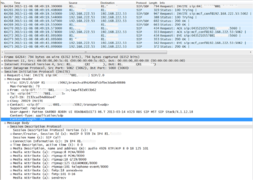
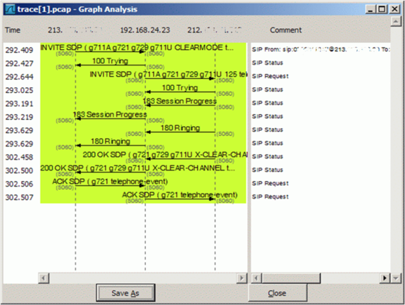
Example of a Wireshark call capture, SIP setup and release:
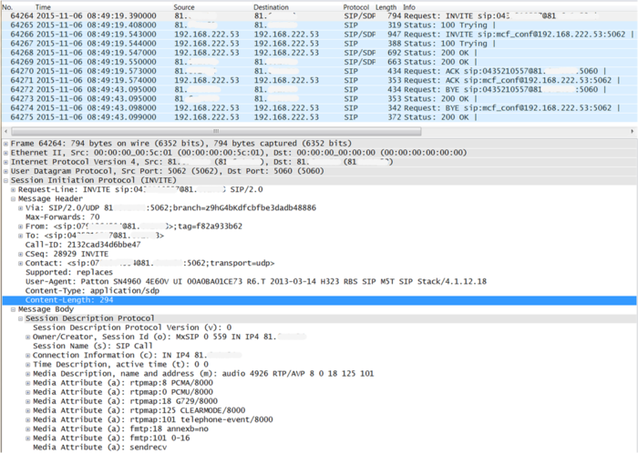
Example of a Wireshark call list:
Navigate in Wireshark:
-
 Menu "Statistics"
-
 Menu "VoIP Calls"
-
Wireshark dialog where all calls are listed of the actual trace:
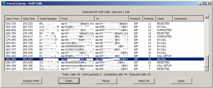
Example of a Wireshark call flow:
Navigate in Wireshark:
-
 Menu "Statistics"
-
 Menu "VoIP Calls"
-
-
 Select the call of interest
-
-
 Click Button [ Graph ]
-
Wireshark dialog where the message flow is shown of the selected call:
The ConfigCenter Call Data
The "Call Data" lists the CDR of all incoming or outgoing connections or connection attempts. Extended filters enable the supporter to search for specific calls. The filters can be combined with logical AND.
Filter CDRs according:
- Call start and end date/time
- Call duration
- Call charges
- Telephone number of caller and/or callee.
- Tenants & account
- Price list attributes "Destination Type" & "Destination"
The "Call Data" has a limited history. The length of the history may be different from VoIP switch to VoIP switch and depends on the CDR storage length in the date base.
Selected CDR details allow direct access to the information of:
- SIP Trace:
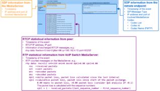
- The SIP message contents of this specific connection or call attempt is shown. For the interpretation of the trace consult the article "Brief Tutorial of the SIP Signaling and SDP Media Protocols", chapter "Knowhow SIP Signaling" .
-
- RTP/RTCP Media:
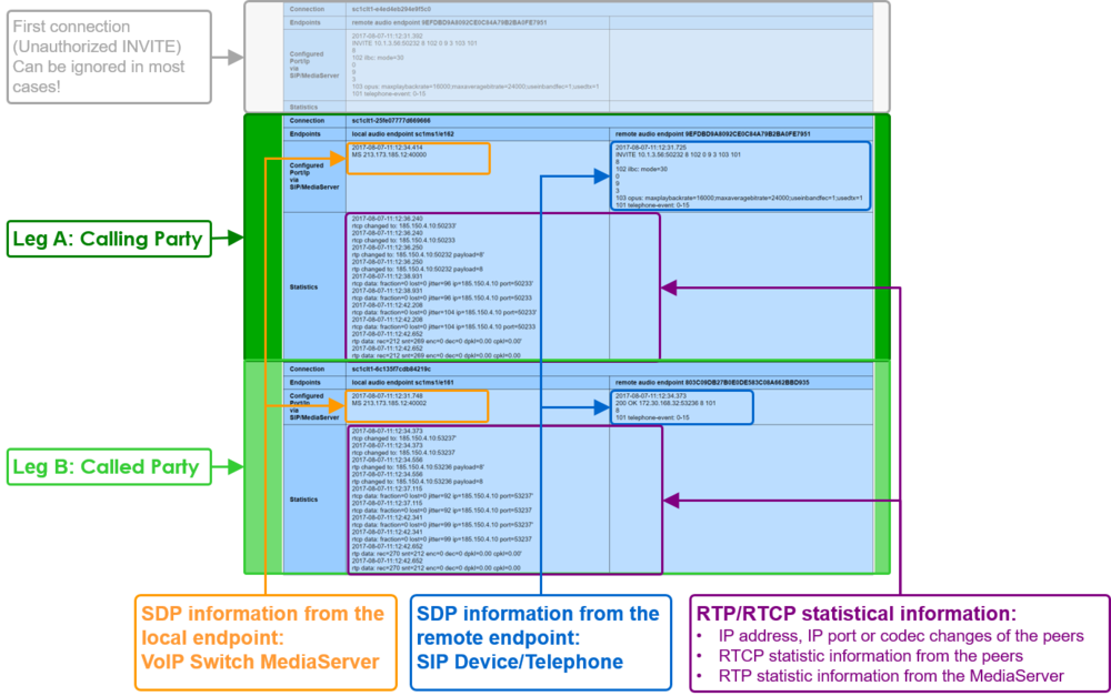
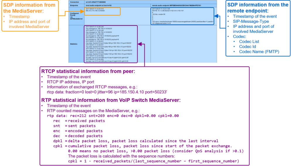
- The RTP/RTCP information and statistics of this specific connection or call attempt is shown. For the interpretation of the media information consult the article "Brief Tutorial of the SIP Signaling and SDP Media Protocols", chapter "Knowhow Media Stream" .
| Note |
|
| Warning |
Depending an the settings of a VoIP system it may be possible to change values in CDR. Changing a CDR's contents may be a legal violation in the country of operation of the VoIP Switch! |
ConfigCenter:
-
 Menu "Rating"
-
 Menu "Call Data"
-
Get the "Call Data"
Dialog: "Call Data":
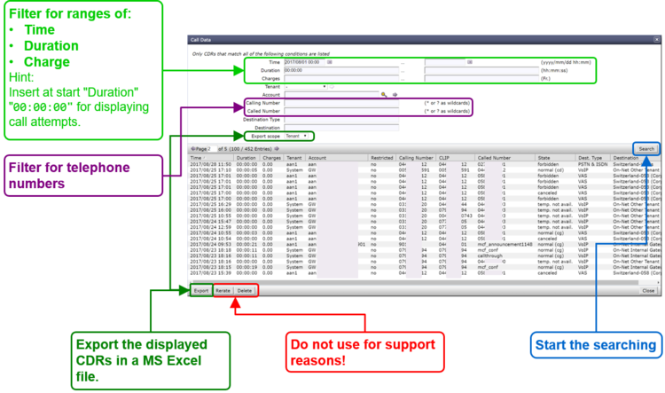
By clicking on the line of a CDR a dialog pops up, which provides a) more details of the connection and b) one click access to the call's SIP trace and media RTP/RTCP information and statistics:
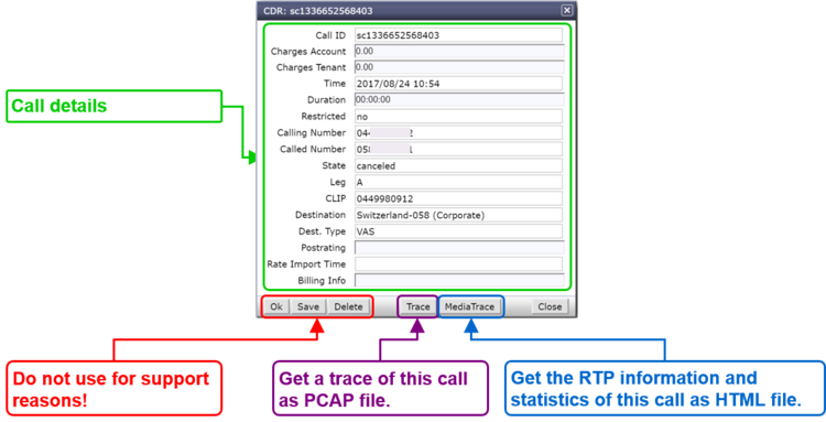
For the interpretation of the trace consult the article:
"Brief Tutorial of the SIP Signaling and SDP Media Protocols", chapter "Knowhow SIP Signaling"For the interpretation of the media information consult the article:
"Brief Tutorial of the SIP Signaling and SDP Media Protocols", chapter "Knowhow Media Stream"
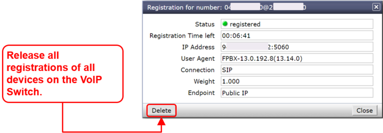
The ConfigCenter Address Registration
The ConfigCenter "Address Registration" displays if a SIP device or MGCP MTA has registered the telephone number. The supporter finds the following information of the registering devices:
- Type of registration, SIP, notifications, presence, etc
- IP address
- SIP user agent
- Registration time left.
Registrations can be de-registrated on the VoIP Switch by force.
Hint:
The device cannot be informed that it was de-registerd on the VoIP Switch. That means you have to wait until it re-registers automatically or force the device manually to re-register.
ConfigCenter:
-
 Menu "Addresses"
or
-
 Menu "Accounts"
-
 Click on the line of the desired account
-
-
 Click on the right arrow at "Addresses"
-
For details:
-
 Click on the line of the desired address
-
-
 Click on the right arrow at "Registration"
-
Interpretation of "Registrations" Information
Display of "Addresses" and registration overview:
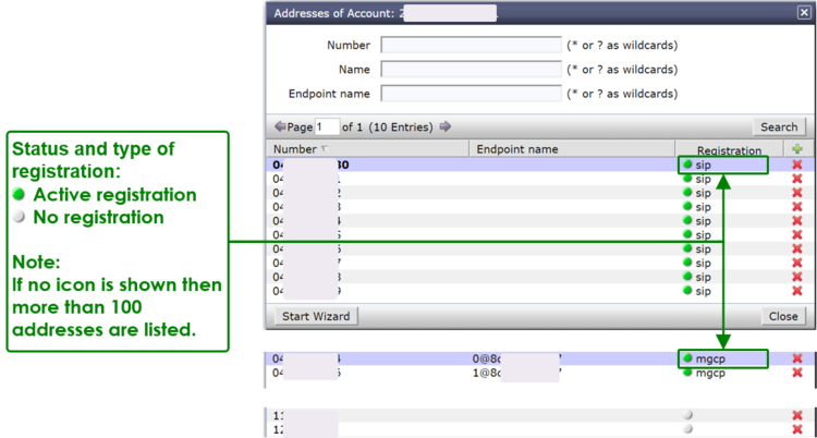
By clicking on the line of an address and then the right arrow at "Registration" a dialog pops up, which provides informations of all registrations of the address:
The ConfigCenter Components
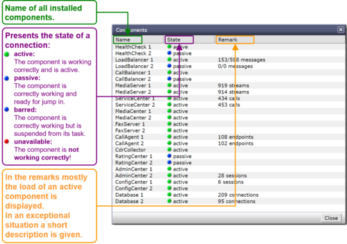
The "Components" displays the state and activity of the VoIP Switch components. The components are the entities of the VoIP Switch that provide all functionality and features. The display is automatically updated every few seconds and shows the actual state and load of every component.
| Note |
On most VoIP Switches the "Components" display is not available for the supporters and operators. |
ConfigCenter:
-
 Menu "System"
-
 Menu "Components"
-
Interpretation of "Components" Information
Display of "Components":
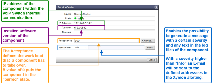
By clicking on the line of a component a dialog pops up, which provides more informations or enables to send messages or handle the work load of the component:
The ConfigCenter Channels
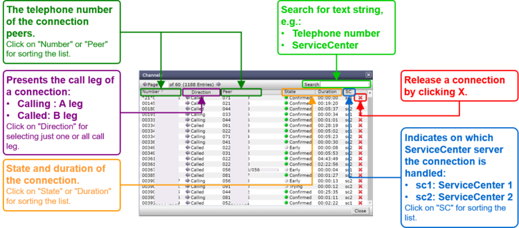
The ConfigCenter "Channels" is a live display of the current active connections and connection build-up. The administrator can filter an search the connections. If needed a connection can be forced to be released.
| Note |
On most VoIP Switches the "Channels" display is not available for the supporters and operators. |
ConfigCenter:
-
 Menu "Channels"
Interpretation of "Channels" Information
Display of "Channels":
The ConfigCenter System Utilization
The "System Utilization" gives a statistical overview of the VoIP Switch resource utilization:
- Number of accounts
- Number of addresses (telephone numbers)
- Number of registrations
- etc
| Note |
On most VoIP Switches the "System Utilization" display is not available for the supporters and operators. |
ConfigCenter:
-
 Menu "System"
-
 Menu "Utilization"
-
Interpretation of the "System Utilization" Information
The "System Utilization" provides the numbers of used resources:
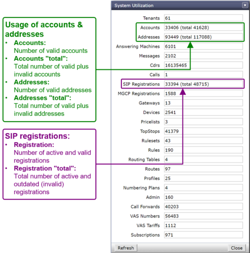
Manual for the Maintenance and Problem Solving of the Aarenet VoIP Switch
VoIP Switch Component Handling
| Warning |
All described actions can jeopardize the VoIP Switch's telephony service or server functionality! If there are uncertainties the contact the "VoIP Switch Supplier Support" |
Basic VoIP Switch Component Commands
The VoIP Switch Administrator finds here instruction for VoIP Switch Component handling on OS console level:
- Start the VoIP Switch Component
- Stop the VoIP Switch Component
- Check the VoIP Switch Component status
- Restart the VoIP Switch Component
- etc
The VoIP Switch Component command affects only the instance on this server and can be executed with root rights only!
Command syntax:
| root# | <AS_COMPONENT> <COMMAND_OPTION> |
Example:
| root# | configcenter status |
| Warning |
Do not use other VoIP Switch Component command options as they can produce heavy problems! |
| Command | Command Option | Remark |
| <AS_COMPONENT>
e.g.:
|
VoIP Switch Component command | |
| version | Lists the VoIP Switch Component version | |
| status | Lists the VoIP Switch Component status and process ID | |
| stop | Stops the VoIP Switch Component
→ The VoIP Switch Component stops immediately and any activity of the component will be interrupted! | |
| start | Starts the VoIP Switch Component
→ The VoIP Switch Component becomes immediately active and operative! | |
| startpassive | Starts the VoIP Switch Component but it remains passive.
→ For becoming operative the VoIP Switch Component has to be started with the start option. | |
| restart | Stops and starts the VoIP Switch Component
→ The VoIP Switch Component becomes immediately active and operative! | |
| restartpassive | Stops and starts the VoIP Switch Component but it remains passive.
→ For becoming operative the VoIP Switch Component has to be started with the start option. | |
| error | Opens the error log file of the VoIP Switch Component | |
| log | Opens the actual log file of the VoIP Switch Component |
Put Out of / Back to Service a VoIP Switch Component in an Operative VoIP Switch
The VoIP Switch Administrator finds here instruction for putting out or back of a VoIP Switch Component.
Put Out of Service a VoIP Switch Component
There are two ways to put out of service a VoIP Switch Component:
Variant 1: "Stop it hard"
Action:
A) Stop and check the component via the shell:
| root# | <AS_COMPONENT> stop |
| root# | <AS_COMPONENT> status |
The consequences are that the component stops immediately its operative work and all its running tasks.
The following VoIP Switch components may be stopped this way without jeopardizing the telephony service:
- ConfigCenter
- AdminCenter
- DataAccessCenter
- MediaCenter
- RatingCenter
- DataBase
| Note |
Make sure that:
|
Variant 2: "Stop it gracefully"
Action:
A) Stop gracefully the component via the ConfigCenter.
For the following components do flip the "active – passive" role:
- HealthCenter
- LoadBalancer
- CallBalancer
do:
- ConfigCenter GUI → Menu "System" → Menu "Components"
- → Click the active component HealthCheck
- → Click the fat right arrow at "Make component passive"
- → Confirm by clicking Button [ Yes ]
- → Click the fat right arrow at "Make component passive"
- → Click the active component HealthCheck
For the following components do a "pre-bar":
- ServiceCenter
- MediaServer
- FaxServer
- CallAgent
do:
- ConfigCenter GUI → Menu "System" → Menu "Components"
- → Click the desired VoIP Switch component
- → Change the parameter "Acceptance" to 0
- → Click the desired VoIP Switch component
C) Wait until the component displays no activity anymore.
- ConfigCenter GUI → Menu "System" → Menu "Components"
D) Stop and check the component via the shell:
| root# | <AS_COMPONENT> stop |
| root# | <AS_COMPONENT> status |
Put Back to Service a VoIP Switch Component
There are two ways to put back to service a VoIP Switch Component:
Variant 1: "Start it"
Action:
A) Start and check the component via the shell:
| root# | <AS_COMPONENT> start |
| root# | <AS_COMPONENT> status |
The consequence is that the component starts immediately its operative work.
Variant 2: "Start it gracefully"
This variant may make sense when the following VoIP Switch components shall become active but not operative immediately:
- ServiceCenter
- MediaServer
- FaxServer
- CallAgent
Action:
A) Start "passive" the component via the ConfigCenter.
| root# | <AS_COMPONENT> startpassive |
| root# | <AS_COMPONENT> status |
B) Make the component operative at the appropriate time:
- ConfigCenter GUI → Menu "System" → Menu "Components"
- → Click the desired VoIP Switch component
- → Change the parameter "Acceptance" to 100
- The "Acceptance" may by any value >0 according. Choose according the load balancing scheme of the component.
- → Click the desired VoIP Switch component
C) Check if the component displays activity:
- ConfigCenter GUI → Menu "System" → Menu "Components"
Work Flow for Analyzing VoIP Switch Problems
| Note |
Not every red alarm jeopardizes the telephony service as a whole but a bulk of yellow warnings may endanger it! |
The VoIP Switch Administrator and other service personnel find here a work flow for analyzing VoIP Switch problem indications and find out the appropriate action.
The main task is to find out if:
- The situation jeopardizes the telephony service as a whole, e.g.:
- IP network issues
- Several VoIP Switch servers failed or off line
- The database replication is broken
- IP network issues
- Server with running database failed
- Linux service MySQL failed
- The situation hampers the operation of configuration of customer accounts, addresses etc.
- Management server failed or off line
- VoIP Switch component ConfigCenter, AdminCenter DataAccessCenter, RatingCenter stopped working correctly
- The situation jeopardizes the telephony service as a whole, e.g.:
The VoIP Switch Administrator finds here the work flow for analyzing VoIP Switch problems:
Analysis:
1. Check if it is a single alarm or a bulk alarm situation.
- a) Connect to the VoIP Switch monitor Xymon "Main View"
- → As a rule of thumb: It is a single error if only one issue is displayed.
2. Analyze and treat a single alarm situation:
- a) Check the contents of the error message.
- b) Compare the error description against the Indication "Xymon Event" ones in chapter "VoIP Switch Maintenance"
- c) Check if the actual situation is equal or similar as described and the recommended actions suitable.
- d) Execute the suitable actions.
- → If you are not sure contact the "VoIP Switch Supplier Support"
3. Analyze the bulk alarm situation:
- a) Get a first overview of the situation by analyzing the Xymon Monitor :
- Check in the MS-01 Xymon monitor the server, component and IP status:
- → Xymon GUI → Xymon "Main View"
- Which type of server are affected?
- At least one LoadBalancer LB server must be active that the telephony service can work!
- At least one ServiceCenter SC server must be active that the telephony service can work!
- At least one server with the operative database must be active that the telephony service can work!
- Check the CPE registration statistic :
- Do drop the CPE registrations?
- Check the call statistic:
- Do drop the VoIP Switch number of calls?
- → Xymon GUI → Management Server → Column "calls_sys"
- Do drop the calls on one or more ServiceCenter?
- → Xymon GUI → ServiceCenter Server → Column "calls_sc"
- Do drop the calls on one or more gateways?
- → Xymon GUI → Gateway → Column "calls_gw"
- Do drop the VoIP Switch number of calls?
- Do the same check as above on MS-02 Xymon Monitor
- Does the comparison of the two Xymon Monitor point out that:
- The same single component on the same server failed?
- All components of one side failed?
- The Xymon Monitor sees only the components on its side?
- The telephony service is running at least on one side
- Which type of server are affected?
- b) Extend the overview by analyzing the ConfigCenter "System Component" Overview :
- Check in the MS-01 ConfigCenter the status of the VoIP Switch components:
- → ConfigCenter GUI → Menu "System" → Menu "Components"
- Are actually calls running and new calls can be established?
- Make test calls:
- To and from a telephone number in the PSTN
- On-net test calls
- Call a well known VoiceMail Box from on-net and from PSTN
- Is the number of running calls fast dropping and no new calls are established?
- Which type of VoIP Switch components are affected?
- At least one LoadBalancer component must be active that the telephony service can work!
- At least one ServiceCenter component must be active that the telephony service can work!
- At least one operative database must be active that the telephony service can work!
- Does this picture correspond to the results of the first overview in the Xymon Monitor ?
- Do the same check as above on MS-02 ConfigCenter
- Does the comparison of the two ConfigCenter point out that:
- The same single component on the same server failed?
- All components of one side failed?
- The ConfigCenter sees only the components on its side?
- The telephony service is running at least on one side
- Are actually calls running and new calls can be established?
4) Treat bulk alarm situations:
- a) Is there a VoIP Switch server hardware, RAID or hard-disk problem?
- → Indications:
| Indication: |
| <HOST_NAME> "snmptrapd" "failure" |
| <HOST_NAME> "snmptrapd" "degraded" |
- → Actions:
- For DELL server see: "Treating Problems of Servers from DELL Inc ®"
- → Actions:
- b) Is the IP connectivity affected to or between VoIP Switch servers?
| Note |
If VoIP Switch servers are affected then a lot of additional alarming messages of missing VoIP Switch components will pop up!!
|
- → Indications:
| Indication: |
| <HOST_NAME> conn "Host does not respond to ping" <IP_ADDRESS> |
* Dropping CPE registrations !
|
- → Actions:
- c) → If you are not sure what to do then contact the "VoIP Switch Supplier Support"
VoIP Switch Server Maintenance
Maintenance Due to VoIP Switch Components General Alarms
Maintenance Due to Messages from Java Framework
Indication "Xymon Event":
Monitor Log, Email or SMTP Trap may contain the following information:
| Indication: |
| <HOST_NAME> msgs "Jdbc" |
Description:
Java internal exceptions. Mostly due to database accesses which are hopefully handled by the application.
Consequences:
→ For the VoIP Switch telephony service:
- Mostly none
→ For the operations:
- Mostly none
→ For the user:
- Mostly none
Solution:
Observe the frequency of this event
Action:
1. Observe the frequency of this event
2. If the erroneous condition is to frequent then contact the "VoIP Switch Supplier Support"!
Maintenance Due to Messages from VoIP Switch Components Internals
Indication "Xymon Event":
Monitor Log, Email or SMTP Trap may contain the following information:
| Indication: |
| <HOST_NAME> msgs "EventQueue" |
| <HOST_NAME> msgs "SysCompDatabase - Cannot evalute status" |
Description:
These events may happen on all VoIP Switch servers and are VoIP Switch component internal notes.
Consequences:
→ For the VoIP Switch telephony service:
- Mostly none
→ For the operations:
- Mostly none
→ For the user:
- Mostly none
Solution:
Observe the frequency of this event
Action:
1. Observe the frequency of this event
2. If the erroneous condition is to frequent then contact the "VoIP Switch Supplier Support"!
Maintenance Due to Messages from LoadBalancer Server
Maintenance Due to HealthCheck Message
Indication "Xymon Event":
Monitor Log, Email or SMTP Trap may contain the following information:
| Indication: |
| <HOST_NAME> msgs "HealthCheck" |
Description:
The HealthCheck supervises the status of virtual IP addresses and their associated physical IP addresses. If the HealthCheck on one server doesn't see the peer physical IP address it takes over the virtual IP address.
It most probably points out an IP network problem in the "Public Voice Segment"
Consequences:
| Warning |
This erroneous condition must be checked within reasonable time! |
→ For the VoIP Switch telephony service:
- None if concurrently no other IP network problems arise
→ For the operations:
- None
→ For the user:
- None
Solution:
Solve the IP network if needed.
Check status the VoIP Switch component with an active-passive scheme:
- LoadBalancer
- CallBalancer
- RatingCenter
Action:
1. Check if the IP network is OK
2. Check the status of the LoadBalancer components
- → Confirm if the active LoadBalancer swapped, e.g. from *-lb-01 to *-lb-02
3. Check the status of the CallBalancer components
- → Confirm if the active CallBalancer swapped, e.g. from *-lb-01 to *-lb-02
4. Check the status of the RatingCenter components
- → Confirm if the active CallBalancer swapped, e.g. from *-ms-01 to *-ms-02
- → Confirm if the active RatingCenter is processing the CDR's
5. Treat the problem:
- a) If there are IP network problems
- → Actions see: "Maintenance Due to IP Network Alarm"
- b) If there is a LoadBalancer problem try to restart the component:
| root# | loadbalancer restart |
- c) If there is a CallBalancer problem try to restart the component:
| root# | callbalancer restart |
- d) If there is a RatingCenter problem try to restart the component:
| root# | ratingcenter restart |
- e) If the RatingCenter swapped make sure that the CDR are processed:
- ConfigCenter GUI → Menu "System" → Menu "Components"
- → Click line at "active" RatingCenter -> In dialog select "Process CDRs"
- → Click button [ Close ]
- → Click line at "active" RatingCenter -> In dialog select "Process CDRs"
- ConfigCenter GUI → Menu "System" → Menu "Components"
- The CDR CSV-Files are processed:
| root# | cd /home/servicecenter/cdrs |
- Check if the CSV files have an actual time stamp which indicates that new CDRs where written:
| root# | ls -ltra |
- Open a CSV file and check for new entries, e.g.:
| root# | less monthly.csv |
6. If the erroneous condition remains then contact the "VoIP Switch Supplier Support"!
- If those events are logged subsequently then rapport it to the "VoIP Switch Supplier Support"!
Maintenance Due to LoadBalancer Message
Indication "Xymon Event":
Monitor Log, Email or SMTP Trap may contain the following information:
| Indication: |
| <HOST_NAME> msgs "Balancer" |
Description:
LoadBalancer internal problem that is treated internally by the component.
The LoadBalancer has an "active-passive" redundancy scheme.
Consequences:
→ For the VoIP Switch telephony service:
- None
→ For the operations:
- None
→ For the user:
- None
Solution:
Not defined yet
Action:
1. If the erroneous condition remains then contact the "VoIP Switch Supplier Support"!
- If those events are logged subsequently then rapport it to the "VoIP Switch Supplier Support"!
Maintenance Due to LoadBalancer Message "Missing ServiceCenter"
Indication "Xymon Event":
Monitor Log, Email or SMTP Trap may contain the following information:
| Indication: |
| <HOST_NAME> msgs "BalancerSwitch" <SERVICECENTER> "not available anymore" |
Description:
The LoadBalancer indicates that it doesn't see a certain ServiceCenter.
This happens when:
- the ServiceCenter has restarted
- → the event will be transient
- the ServiceCenter is stopped
- → the event will remain until the ServiceCenter is started again
- no IP connectivity
- → the event will remain until the IP connectivity is reestablished
Consequences:
| Warning | This erroneous condition must be handled within reasonable time! |
→ For the VoIP Switch telephony service:
- None, the other ServiceCenter take over the work load
- If a ServiceCenter is missing then the VoIP Switch looses redundancy capability
→ For the operations:
- None
→ For the user:
- None
Solution:
Solve the IP network problems if needed:
- → Actions see: "Maintenance Due to IP Network Alarm"
Solve the server problem if needed
- → Actions see: "Treating Server Hardware Problems"
Action:
1. Check if the IP network is OK
2. Check the status of the ServiceCenter components
- → Confirm that the reported ServiceCenter server is affected
3. Check the reported ServiceCenter server with the "Server Administrator (OMSA)"
4. Treat the problem:
- a) If there are IP network problems
- → Actions see: "Maintenance Due to IP Network Alarm"
- b) If there is a ServiceCenter problem try to restart the component:
| root# | servicecenter restart |
5. If the erroneous condition remains then contact the "VoIP Switch Supplier Support"!
Maintenance Due to CallBalancer Message
Indication "Xymon Event":
Monitor Log, Email or SMTP Trap may contain the following information:
| Indication: |
| <HOST_NAME> msgs |
Description:
The CallAgent dispatches MGCP messages to the CallAgent components.
The CallAgent has an "active-passive" redundancy scheme.
Consequences:
| Warning |
This erroneous condition must be checked within short time! |
→ For the VoIP Switch telephony service:
- None
→ For the operations:
- None
→ For the user:
- Users with MGCP MTA as telephone adapter may not be able to telephone
Solution:
Check status the CallBalancer active-passive scheme and if the MGCP messages are processed.
Action:
1. Check if the IP network is OK
2. Check the status of the CallBalancer components:
- a) Confirm if the active CallBalancer swapped , e.g. from *-ms-01 to *-ms-02
- b) Confirm if the active CallBalancer is processing the MGCP messages
- → Check if the CallAgent treat MGCP connections and that the total number of MGCP connections is not dropping.
3. Check if the MGCP audits are not dropping:
- a) Connect to a Xymon monitor and check in Xymon Column "regs" the numbers of MGCP-Active and MGCP-Brocken
- b) Check the questions:
- Do drop the number of MGCP-Active?
- → If yes => There may be a IP backbone problem or CallBalancer, CallAgent outage!
4. Treat the problem:
- a) If there are IP network problems
- → Actions see: "Maintenance Due to IP Network Alarm"
- b) If there is a CallBalancer problem try to restart the component:
| root# | callbalancer restart |
5. If the erroneous condition remains then contact the "VoIP Switch Supplier Support"!
Maintenance Due to MediaServer Message
Indication "Xymon Event":
Monitor Log, Email or SMTP Trap may contain the following information:
| Indication: |
| <HOST_NAME> msgs "MediaConnection (06) Cannot handle outgoing message" |
| <HOST_NAME> msgs "MediaServerProvider (MS) refreshing mediaserver mc1ms2 failed" |
Description:
The MediaServer records or plays back announcements and VoiceMail messages. Occasionally it may not correctly record a message and transfer it to the MediaCenter or play back an announcement or message.
The MediaServer can act as media proxy for active connections and transcode media streams.
Consequences:
| Warning |
If in this VoIP Switch the MediaServer acts as media proxy then the erroneous situation must be checked soon! |
→ For the VoIP Switch telephony service:
- None
→ For the operations:
- None
→ For the user:
- A VoiceMail Box message or announcement couldn't correctly record or played back.
- User may not hear the other side or vica versa.
Solution:
Depends on the situation.
Action:
1. If the erroneous condition remains or happens to often then contact the "VoIP Switch Supplier Support"!
Maintenance Due to Messages from Management Server
Maintenance Due to AdminCenter Message "Missing FMC Application Server"
Indication "Xymon Event":
Monitor Log, Email or SMTP Trap may contain the following information:
| Indication: |
| <HOST_NAME> msgs "FmcRequest - Cannot post request" |
| <HOST_NAME> msgs "FmcProvider - could not provision pbx" |
Description:
The AdminCenter tried to configure the FMC application.
Consequences:
| Warning |
This erroneous condition is sporadic or must be handled within reasonable time! |
→ For the VoIP Switch telephony service:
- None
→ For the operations:
- A configuration on a FMC server failed
→ For the user:
- A user "an MC-Phone" is not working
Solution:
Check the state of the FMC servers and their IP connectivity toward the VoIP Switch servers.
Action:
1. Check if the IP network is OK
2. Check the status of the FMC server
3. Treat the problem:
- a) If there are IP network problems
- → Actions see: "Maintenance Due to IP Network Alarm"
- b) If there is a FMC server problem
- → Contact the "VoIP Switch Supplier Support"!
4. If the erroneous condition remains then contact the "VoIP Switch Supplier Support"!
Maintenance Due to AdminCenter Message "Missing Redirection Server"
Indication "Xymon Event":
Monitor Log, Email or SMTP Trap may contain the following information:
| Indication: |
| <HOST_NAME> msgs "FmcProvider - could not provision user" <USER_TELEPHONE_NUMBER> |
Description:
The mobile app "an MC-Phone" couldn't get the information from the associated redirection server (by default a Comdasys server located in Europe) where its responsible configuration server is located. Therefore the users "an MC-Phone" couldn't obtain its configuration and will not work.
Consequences:
→ For the VoIP Switch telephony service:
- None
→ For the operations:
- None
→ For the user:
- The mobile app "an MC-Phone" will not work
Solution:
Make sure to have good IP connectivity to the Internet
Action:
1. The user must find a reliable Internet connection and restart the app "an MC-Phone" until it gets its configuration
Maintenance Due to ConfigCenter Message "Wrong User Login"
Indication "Xymon Event":
Monitor Log, Email or SMTP Trap may contain the following information:
| Indication: |
| <HOST_NAME> msgs "msgsAccessLogger - ADMIN:login; user" <USERNAME> "-> User Blocked" |
Description:
A VoIP Switch Administrator, Operator, Supporter tried to login to the ConfigCenter with wrong credentials.
The user will be blocked for several minutes.
Consequences:
→ For the VoIP Switch telephony service:
- None
→ For the operations:
- The user will be blocked from the ConfigCenter for several minutes.
→ For the user:
- None
Solution:
Wait
Action:
1. Retry after a few minutes with the correct login credentials.
2. If the erroneous condition remains then contact the "VoIP Switch Supplier Support"!
Maintenance Due to ConfigCenter Message "DB Replication Check"
Indication "Xymon Event":
Monitor Log, Email or SMTP Trap may contain the following information:
| Indication: |
| <HOST_NAME> msgs JdbcReplicationMonitor "Replication" '<BROKEN_REPLICATION_DIRECTION>' "is broken!" |
Description:
The database replication check was not successful. This can happen from time to time when the database has to process heavy load.
In most cases the database replication recovers automatically even after several hours of failed replication. If it is not recovering then this is a severe problem and must be treated.
Consequences:
| Warning | If this erroneous condition remains then this is a SEVERE erroneous condition and must be treated within short time! |
→ For the VoIP Switch telephony service:
- The database redundancy is endangered
→ For the operations:
- None
→ For the user:
- None
Solution:
Restore the MySQl DB replication if the erroneous condition remains.
Action:
1. Check periodically (ca. every half hour) the Xymon monitor for this error condition.
2. If the erroneous condition remains then contact the "VoIP Switch Supplier Support"!
Maintenance Due to DataAccessCenter Message
Indication "Xymon Event":
Monitor Log, Email or SMTP Trap may contain the following information:
| Indication: |
| <HOST_NAME> msgs "Jdbc" "SQL-Exception during statement" |
Description:
A configuration via the DataAccessCenter may have failed.
This may happen if the database is under heavy load.
Consequences:
| Warning | This erroneous condition must be checked within reasonable time! |
→ For the VoIP Switch telephony service:
- None
→ For the operations:
- A customer configuration may have failed (which is hopefully covered by the CRM application).
→ For the user:
- None
Solution:
Inter-working between the DataAccessCenter and database must be optimized.
Action:
1. If this Java event is logged subsequently then rapport it to the "VoIP Switch Supplier Support"!
Maintenance Due to RatingCenter Message
Indication "Xymon Event":
Monitor Log, Email or SMTP Trap may contain the following information:
| Indication: |
| <HOST_NAME> msgs |
Description:
The RatingCenter has an "active-passive" scheme. Every RatingCenter event has to be checked if the active RatingCenter is working correctly and is processing the CDRs.
Consequences:
| Warning |
This erroneous condition must be checked within short time! |
→ For the VoIP Switch telephony service:
- None
→ For the operations:
- A CDR may be not written correctly into the CDR database and/or CSV files.
- The customer billing contains not all CDR
→ For the user:
- None
Solution:
Check status the RatingCenter active-passive scheme and if the CDR are processed.
Action:
1. Check the status of the RatingCenter component
- → Confirm if the active RatingCenter is processing the CDR's
2. Treat the problem:
- a) If the RatingCenter swapped make sure that the CDR are processed:
- → Open the ConfigCenter Menu "Components"
- → Click line at "active" RatingCenter -> In dialog select "Process CDRs"
- → Click button [ Close ]
- → Click line at "active" RatingCenter -> In dialog select "Process CDRs"
- → Open the ConfigCenter Menu "Components"
- b) Check if the CDR CSV-Files are processed:
- Open the CDR directory:
| root# | cd /home/ratingcenter/cdrs |
- Check if the CSV files have an actual time stamp which indicates that new CDRs where written:
| root# | ls -ltra |
- Open a CSV file and check for new entries, e.g.:
| root# | less monthly.csv |
3. If the erroneous condition remains then contact the "VoIP Switch Supplier Support"!
Maintenance Due to Messages from ServiceCenter Server
Maintenance Due to FaxServer Message
Indication "Xymon Event":
Monitor Log, Email or SMTP Trap may contain the following information:
| Indication: |
| <HOST_NAME> msgs |
Description:
Fax may not received correctly. The mailing of the PDF file may fail.
Consequences:
→ For the VoIP Switch telephony service:
- None
→ For the operations:
- None
→ For the user:
- A received Fax may not be correctly received and transferred to the user. This situation is usually handled by the Fax device either automatically or manually.
Solution:
Restart the FaxServer component.
Action:
1. Check if no Fax at all are received.
- → Send test fax.
2. Restart the FaxServer:
| root# | faxserver restart |
3. If the FaxServer logs subsequently then rapport it to the "VoIP Switch Supplier Support"!
Maintenance Due to MediaCenter Message
Indication "Xymon Event":
Monitor Log, Email or SMTP Trap may contain the following information:
| Indication: |
| <HOST_NAME> msgs MediaCenterCall |
| <HOST_NAME> msgs MediaServer |
| <HOST_NAME> msgs "file not found" |
Description:
The MediaCenter handles the WAV files from announcements and VoiceMail messages. Occasionally it may not correctly record a message, loose a message file. Also an order to the MediaServer may fail to replay a message or announcement.
Consequences:
→ For the VoIP Switch telephony service:
- None
→ For the operations:
- None
→ For the user:
- A VoiceMail Box message or announcement couldn't correctly recorded or played back
Solution:
Clean up the VioceMail message date base.
Optimize the inter-working of MediaCenter and MediaServer
Action:
1. If those events are logged subsequently then rapport it to the "VoIP Switch Supplier Support"!
Maintenance Due to ServiceCenter Message
Indication "Xymon Event":
Monitor Log, Email or SMTP Trap may contain the following information:
| Indication: |
| <HOST_NAME> msgs |
Description:
The ServiceCenter is the main component of the VoIP Switch. It computes the connections signaling and telephony features.
The ServiceCenter has an all active redundancy scheme. If one ServiceCenter fails the remaining ServiceCenter take over the work load.
Consequences:
| Warning | This erroneous condition must be checked and treated within short time! |
→ For the VoIP Switch telephony service:
- As long one ServiceCenter remains the VoIP Switch works!
→ For the operations:
- None
→ For the user:
- None
Solution:
Depends on the analyzed problem.
Action:
1. Check how acute the problem is:
- a) Check if the IP network is OK
- b) Check the status of the ServiceCenter component
- Are enough ServiceCenter active that the work load can be treated?
- → If NO then there is a most SEVERE erroneous situation
- c) Check in the ConfigCenter Menu "Components" if the active ServiceCenter is processing the connections:
- Do drop the total number of connections?
- → If YES then there is a most SEVERE erroneous situation:
- → There may be a IP backbone problem!
- d) Check in the Xymon Column "regs" the number of registered SIP-Devices:
- Do drop the number of SIP-Devices?
- → If YES then there is a most SEVERE erroneous situation:
- → There may be a IP backbone problem!
- e) Check the reported ServiceCenter server with the "Server Administrator (OMSA)"
- Are problems signaled?
2. Treat the problem:
- a) If there are IP network problems
- → Actions see: "Maintenance Due to IP Network Alarm"
- b) If there is a ServiceCenter problem try to restart the component:
| root# | servicecenter restart |
- c) If there is a hardware problem:
- → Actions see: "Treating Server Hardware Problems"
3. If the erroneous condition remains then contact the "VoIP Switch Supplier Support"!
Maintenance Due to ServiceCenter Message "License Violation"
Indication "Xymon Event":
Monitor Log, Email or SMTP Trap may contain the following information:
| Indication: |
| <HOST_NAME> msgs License "License Violation" |
| <HOST_NAME> msgs License "grace-period remaining:" |
Description:
This ServiceCenter has a license problem and will work only for the remaining grace period.
Consequences:
| Warning |
This erroneous condition must be checked and treated within the remaining grace period! |
→ For the VoIP Switch telephony service:
- As long one ServiceCenter remains the VOIP Switch works
- The telephony service will be stopped on this ServiceCenter after passing of the grace period
→ For the operations:
- None
→ For the user:
- None
Solution:
Get actual licenses from the VoIP Switch Supplier.
Action:
1. Check in the ConfigCenter Menu "Components" which ServiceCenter component has a license problem and how long the grace period is.
2. Contact the "VoIP Switch Supplier Support"!
Maintenance Due to ServiceCenter Message "Failed Emergency Call"
Indication "Xymon Event":
Monitor Log, Email or SMTP Trap may contain the following information:
| Indication: |
| <HOST_NAME> msgs ServicePrioCallControl "Could not establish priority-call". Call from Connection/<SIP_CALL_ID>/<CALLING_NUMBER> to <CALLED_EMERGENCY_NUMBER> |
Description:
A user's emergency call failed!
Consequences:
| Warning | Severe legal condition that must be handled!
This case can have legal consequences for the provider! |
→ For the VoIP Switch telephony service:
- None
→ For the operations:
- None
→ For the user:
- The emergency call did not work
Solution:
Check if the call routing failed due to a VoIP Switch emergency call treating or routing. If yes fix them.
Check if the PSTN provider did reject the emergency call. If yes contact the PSTN provider.
Action:
1. Archive traces for legal responsibilities:
- Save the trace of this emergency call and all subsequent calls from this user toward emergency numbers
2. Check where the call was rejected.
- If the call was rejected at the PSTN provider side contact the PSTN provider and let investigate into this case.
3. Check the VoIP Switch's emergency routing:
- Emergency numbers
- Emergency number rewriter
- Routing Tables toward the PSTN
- RuleSet that may tag outgoing calls toward emergency numbers
4. Check if any IP network devices may interfere with the SIP signaling:
- If there are external Session Board Controller SBC or SIP-SS7 Gateway involved check their behavior concerning the emergency calls
- If a firewall FW is involved check that no SIP ALG or "SIP Helpers" are active
5. Treat the problem:
- a) Adjust the emergency routing of the VoIP Switch if needed
- b) Fix the IP network devices if needed
6. If the erroneous condition remains then contact the "VoIP Switch Supplier Support"!
Maintenance Due to ServiceCenter Message "TopStop"
Indication "Xymon Event":
Monitor Log, Email or SMTP Trap may contain the following information:
| Indication: |
| <HOST_NAME> msgs ServiceRatingControl (01) <CALLING_NUMBER> "max available charges reached for account:" |
| <HOST_NAME> msgs AlarmLogger "[TOPSTOP][ALARM] tenant" <TENANT> "topstop limit nearly reached for account" |
Description:
A user's TopStop limit was reached!
| Note |
A TopStop alarm early in the month or for a lot of users indicates a possible fraud case! |
Consequences:
→ For the VoIP Switch telephony service:
- None
→ For the operations:
- A TopStop alarm early in the month indicates a possible fraud case
→ For the user:
- No outgoing calls except emergency call will work when the TopStop limit is reached
Solution:
If it is a regular TopStop then contact the user and enhance the monthly TopStop limit.
If it is a fraud situation handle according "Best Practice: Fraud"
Action:
1. Check if it is a regular TopStop situation.
2. Check if it is a possible fraud case:
- Reached TopStop limit early in the month?
- Concurrently a lot of TopStop limits reached?
- High call peak during the night or weekend?
- → Check at Xymon Column " calls_sys " .
3. Treat according " Best Practice for "Fraud Situation"
4. If the erroneous condition remains then contact the "VoIP Switch Supplier Support"!
Maintenance Due to Nimbus Message
Indication "Xymon Event":
Monitor Log, Email or SMTP Trap may contain the following information:
| Indication: |
| <HOST_NAME> msgs "NimbusLink (ue) Cannot subscribe" |
Description:
The Nimbus component is a VoIP Switch internal bus that connects the various VoIP Switch components on the servers. If a Nimbus endpoint on one server is missing the other Nimbus endpoints start to complain.
If a Nimbus endpoint is missing then the component may be stopped, the server not on line or an IP network problem.
- → This error is often displayed during VoIP Switch software upgrades of the servers. In this situation just wait until the upgrade is finished.
Consequences:
| Warning |
This erroneous condition must be checked and treated within reasonable time! |
→ For the VoIP Switch telephony service:
- Usually none
→ For the operations:
- None
→ For the user:
- None
Solution:
Solve the IP network problems or server problems if needed.
Action:
1. Check if the IP network is OK
2. Check the status of the VoIP Switch components located on the server where the Nimbus is missing:
- → Is only Nimbus missing or other components to on this server?
3. Treat the problem:
- a) If there are IP network problems
- → Actions see: "Maintenance Due to IP Network Alarm"
- b) If there is not a planned outage then try to solve the server problem
- c) If there is not a planned outage then try to restart the Nimbus on this server:
| root# | nimbus restart |
4. If the erroneous condition remains then contact the "VoIP Switch Supplier Support"!
Maintenance Due to Messages from CallAgent Server
Maintenance Due to CallAgent Message
Indication "Xymon Event":
Monitor Log, Email or SMTP Trap may contain the following information:
| Indication: |
| <HOST_NAME> msgs |
Description:
The CallAgent treats the message exchange with the MGCP MTA.
The CallAgent has an all active redundancy scheme. If one CallAgent fails the remaining CallAgent take over the work load.
Consequences:
| Warning |
This erroneous condition must be checked within short time! |
→ For the VoIP Switch telephony service:
- As long one CallAgent remains the VOIP Switch works
→ For the operations:
- None
→ For the user:
- Single MGCP MTA at the user's premises is not working correctly. The telephone service may not always work for this users.
Solution:
Depends on the analyzed problem.
Action:
1. Check if the IP network is OK
2. Check the status of the CallAgent components
- → Confirm that the reported CallAgent server is affected
3. Check the reported CallAgent server with the "Server Administrator (OMSA)"
4. Treat the problem:
- a) If there are IP network problems
- → Actions see: "Maintenance Due to IP Network Alarm"
- b) If there is a CallAgent problem try to restart the component:
| root# | callagent restart |
5. If the erroneous condition remains then contact the "VoIP Switch Supplier Support"!
Maintenance Due to Messages from CPECenter Server
Maintenance Due to CpeCenterMessage
Indication "Xymon Event":
Monitor Log, Email or SMTP Trap may contain the following information:
| Indication: |
| <HOST_NAME> msgs |
| <HOST_NAME> msgs "DevAdmProvider (-1) duplicated devicetype:" <DEVICE_TYPE> |
Description:
During the preparation of a device configuration file two device configuration templates were found.
If a CPE loads a device configuration file which was produced under these conditions it may not work correctly.
Consequences:
→ For the VoIP Switch telephony service:
- None
→ For the operations:
- None
→ For the user:
- The CPE may not work with the produced configuration file
Solution:
One device configuration template has to be deleted.
Action:
1. Contact the "VoIP Switch Supplier Support"!
Maintenance Due to IP Network Alarms
Indication "Xymon Event":
Monitor Log, Email or SMTP Trap may contain the following information:
| Indication: |
| <HOST_NAME> conn "Host does not respond to ping" <IP_ADDRESS> |
Description:
This test performs a "ping" toward the IP address of the host. If the "ping" is not answered then there is a problem with the IP network, e.g.:
- Pinged host defect or off line
- Layer2 IP Switch defect or off line
- Brocken IP backbone network
Consequences:
| Warning |
MOST SEVERE condition if several VoIP Switch server are affected for a longer duration (ca 15min)! |
→ For the VoIP Switch telephony service:
- The telephone service may be interrupted
→ For the operations:
- The MySQL databases may loose their replication
→ For the user:
- The telephone service may be interrupted for the users!
Solution:
Solve the IP network problems!
Check the IP network devices:
- Pinged host
- Layer 2 IP switches
- IP Routes
- Firewalls
Check the VoIP Switch server IP connectivity.
Action:
1. Evaluate the severity of the IP network outage:
- a) Check if it is a occasional ping failure:
- Only one host doesn't respond
- Only 1 or 2 poll cycle fail
- → Type "Occasional Failure":
- In this situation the erroneous situation may be neglected.
- b) Check if it is only a single host:
- One host doesn't respond anymore
- → Type "Host Failure":
- Check the hardware condition and IP connectivity of this device
- Check with the VoIP Switch Administrator in the ConfigCenter Menu "Components" how the VoIP Switch is affected
- c) Check if more than one VoIP Switch server is affected:
- More than one VoIP Switch server don't respond anymore
- → Type "VoIP Switch Failure":
- 1. Check with the VoIP Switch Administrator how the VoIP Switch is affected:
- a) Connect to both (*-ms-01, *-ms-02) ConfigCenter Menu "Components" and check the component status
- b) Check the questions:
- Which VoIP Switch servers are not visible?
- Are they the same on both ConfigCenter?
- b) Check the questions:
- Does one ConfigCenter see only the servers on its side? E.g.:
- Side A components complain that they doesn't see their peers on Side B?
- Side B components complain that they doesn't see their peers on Side A?
- → If yes => There is a heavy IP backbone problem
- c) Check in the ConfigCenter Menu Channles if new connections were established since the IP outage
- → If yes => Some users still can make phone calls
- c) Check in the ConfigCenter Menu Channles if new connections were established since the IP outage
- 2. Check with the VoIP Switch Administrator how the users are affected:
- a) Connect to both (*-ms-01, *-ms-02) Xymon Column "regs" and check the CPE and MTA registrations status.
- 2. Check with the VoIP Switch Administrator how the users are affected:
- b) Check the questions:
- Check: Do drop the user's CPE registration?
- → If yes => There is a heavy IP backbone problem some users cannot use the telephony service anymore!
- b) Check the questions:
3. Treat the Type "VoIP Switch Failure":
- a) VoIP Switch Administrator:
- In this situation the erroneous situation may be neglected. Observe if the situation remains.
2. Treat the Type " Occasional Failure ":
- a) VoIP Switch Administrator:
- If possible pre-bar the VoIP Switch component on this server
- b) Solve the IP or hardware issue with the failed host
3. Treat the Type "VoIP Switch Failure":
- a) VoIP Switch Administrator:
- Contact the "VoIP Switch Supplier Support"
4. If the erroneous condition remains then contact the "VoIP Switch Supplier Support"!
Maintenance Due to Operating System Alarms
The VoIP Switch Administrator and/or server service personnel find here instructions for managing problems indicated by the operating system supervision.
Maintenance Due to Supervised Processes Missing
Indication "Xymon Event":
Monitor Log, Email or SMTP Trap may contain the following information:
| Indication: |
| <HOST_NAME> procs "Processes not OK" <MISSING_PROCESS> |
Description:
One or more supervised process of a Linux service or VoIP Switch component is missing.
Consequences:
| Warning |
SEVERE erroneous condition that must be handled! |
→ For the VoIP Switch telephony service:
- Depends If a VoIP Switch component is missing then the VoIP Switch looses redundancy capability
- If a Linux service is missing the VoIP Switch may be hampered or the server is not working correctly
→ For the operations:
- Depends on the VoIP Switch components or Linux service
→ For the user:
- Depends on the VoIP Switch components or Linux service
Solution:
Restart the VoIP Switch component or Linux service.
Action:
1. Check with the VoIP Switch Administrator if it is possible to restart the component or service without endangering the VoIP Switch telephony service.
- → If possible pre-bar the VoIP Switch component via the ConfigCenter!
2. Restart the VoIP Switch component or Linux service:
| root# | <COMPONENT> restart |
- Example:
| root# | servicecenter restart |
- b) Restart the service:
| root# | /etc/init.d/<SERVICE> restart |
- Example:
| root# | monit restart |
3. If the erroneous condition remains then contact the "VoIP Switch Supplier Support"!
Maintenance Due to Supervised IP Ports
Indication "Xymon Event":
Monitor Log, Email or SMTP Trap may contain the following information:
| Indication: |
| <HOST_NAME> ports "Ports not OK" <MISSING_PROCESS_PORTS> |
Description:
One or more supervised IP port of a Linux service or VoIP Switch component is missing.
Consequences:
| Warning |
SEVERE erroneous condition that must be handled! |
→ For the VoIP Switch telephony service:
- Depends If a VoIP Switch component is missing then the VoIP Switch looses redundancy capability
- If a Linux service is missing the VoIP Switch may be hampered or the server is not working correctly
→ For the operations:
- Depends on the VoIP Switch components or Linux service
→ For the user:
- Depends on the VoIP Switch components or Linux service
Solution:
Restart the VoIP Switch component or Linux service.
Action:
1. Check with the VoIP Switch Administrator if it is possible to restart the component or service without endangering the VoIP Switch telephony service.
- → If possible pre-bar the VoIP Switch component via the ConfigCenter!
2. Restart the VoIP Switch component or Linux service:
| root# | <COMPONENT> restart |
- Example:
| root# | servicecenter restart |
- b) Restart the service:
| root# | /etc/init.d/<SERVICE> restart |
- Example:
| root# | monit restart |
3. If the erroneous condition remains then contact the "VoIP Switch Supplier Support"!
Maintenance Due to Supervised Hard-Disk Usage
Indication "Xymon Event":
Monitor Log, Email or SMTP Trap may contain the following information:
| Indication: |
| <HOST_NAME> disk "File systems not OK" |
Description:
A hard-disk or hard-disk partition is full.
If a hard-disk is full then the Linux operating system behaves unpredictable and the server will most probably crash.
Consequences:
| Warning | SEVERE erroneous condition that must be handled! |
→ For the VoIP Switch telephony service:
- Depends on the VoIP Switch components running on the server
→ For the operations:
- Depends on the VoIP Switch components running on the server
→ For the user:
- Depends on the VoIP Switch components running on the server
Solution:
Identify big files or directories. Delete or archive files externally.
Action:
1. Check hard-disk usage:
| root# | df -h |
2. Find fat files:
| root# | ls -lahS $(find / -type f -size +100k) |
- Example find file sizes >60MByte:
| root# | ls -lahS $(find /opt/backup/ -type f -size +60000k) |
- Check for fat files in the following suspicious directories:
- /opt/backup/
- Check for fat files in the following suspicious directories:
- Do not touch big files in:
- /var/lib/mysql/
- Do not touch big files in:
3. Find big directories:
| root# | du -hs |
- Example of a more specific search → find directory sizes >1GByte:
| root# | du -hs /home/ratingcenter/* | grep G |
| root# | du -hs /home/*/* | grep G |
- Check the following suspicious directories:
- /opt/backup/
- /home/mediacenter/messages
- //home/ratingcenter/cdrs
- Check the following suspicious directories:
4. Prior of deleting files or directories check with the VoIP Switch Administrator if they are not needed anymore!
- → If you are suspicious but not sure if it is wise to delete a certain file or directory then contact the "VoIP Switch Supplier Support"!
Maintenance Due to Supervised Memory Usage
Indication "Xymon Event":
Monitor Log, Email or SMTP Trap may contain the following information:
| Indication: |
| <HOST_NAME> memory "Memory low" |
Description:
One or more processes consume a lot of memory space. If the memory becomes low the operating system Linux
start to swap memory to and from hard-disk. This reduces the performance of the server.
Consequences:
| Warning |
This erroneous condition must be handled within reasonable time! |
→ For the VoIP Switch telephony service:
- Depends on the VoIP Switch components running on the server
→ For the operations:
- None
→ For the user:
- None
Solution:
Identify which process or consumes the memory. Restart the process in order to free memory.
Stop and restart the swapping on the server.
Action:
1. If a LoadBalancer *-lb-* or ServiceCenter *-sc-* server is affected:
- → Contact the "VoIP Switch Supplier Support"!
2. Find which processes use the memory:
- This is a difficult task!
| root# | top |
3. Stop and restart the swapping:
- Preconditions:
- Choose a day time where the server is not in high load.
- If possible pre-bar the VoIP Switch components on this server via the ConfigCenter
- Make sure that the redundant VoIP Switch component is running
- a) Restart the responsible process:
| root# | /etc/init.d/<PROCESS_NAME> restart |
- b) Stop the swapping:
- Don't do this during high load!
- It will take some time until accomplished!
| root# | swapoff -a |
- c) Restart the swapping:
| root# | swapon -a |
- d) Check if the swap is working regularly:
| root# | swapon -s |
Maintenance Due to Supervised CPU Load
Indication "Xymon Event":
Monitor Log, Email or SMTP Trap may contain the following information:
| Indication: |
| <HOST_NAME> cpu "Load is High" |
Description:
One or more processes consume extensively CPU power. This may reduce the performance of the server.
Consequences:
| Warning | This erroneous condition must be handled within reasonable time! |
→ For the VoIP Switch telephony service:
- Reduced performance on the affected server and VoIP Switch component
→ For the operations:
- None
→ For the user:
- None
Solution:
The CPU consuming process has to be identified. If a process is identified it has to be checked if it is a regular or erroneous situation.
If it is a regular situation then it has to be investigated if the servers computing power is still sufficient for this VoIP Switch. If the server hosts a VoIP Switch component which offers an configurable load acceptance via the ConfigCenter then it is worth a try to reduce the components workload.
An erroneous situation can mostly be solved by restarting the process.
Action:
1. Identify the responsible process:
- a) Check the process situation with:
| root# | top |
| root# | ps aux |
- b) If a process is suspicious check for multiple processes of the same name:
| root# | ps -aef |
- c) If a process is suspicious check for zombie processes (lists the zombie process id):
| root# | ps aux |
- d) Evaluate with the VoIP Switch Administrator if the suspicious process is in a regular or erroneous state.
2. Handle an erroneous Linux process state.
- a)* Restart a Linux process:
| root# | /etc/init.d/<PROCESS_NAME> restart |
b) Kill a process, e.g. double started process, zombie:
| root# | kill -9 <PROCESS_ID> |
3. Handle a VoIP Switch component :
- a) Restart an erroneous VoIP Switch component:
| root# | <COMPONENT_NAME> restart |
- b) If the VoIP components ServiceCenter or MediaServer produces high load then the VoIP Switch Administrator may reduce their accepted work load via the ConfigCenter.
4. If the erroneous condition remains then contact the "VoIP Switch Supplier Support"!
Maintenance Due to Supervised Files Missing or to Big
Indication "Xymon Event":
Monitor Log, Email or SMTP Trap may contain the following information:
| Indication: |
| <HOST_NAME> ???? |
Description:
Consequences:
→ For the VoIP Switch telephony service:
- None
→ For the operations:
- None
→ For the user:
- None
Solution:
Action:
1. If the erroneous condition remains then contact the "VoIP Switch Supplier Support"!
VoIP System Maintenance
Best Practice for Handling a "Fraud" Situation
The Aarenet VoIP Switch Administrator finds here instructions for managing fraud problems.
1. Immediate action:
- Block call routing to the destination (usually somewhere in the Caribbean, west or central Africa)
- If only from one source IP address then block this IP address on the FW
2. Investigate if the fraud is due to "Direct Registrations" with correct SIP credentials on the VoIP Switch:
- Check if the calling number has multiple SIP registrations of a suspicious source IP range or user agent!
- → If YES then:
- → The SIP credentials were not kept secret or hacked from the users CPE
- Action:
- Block this user account for outgoing calls (blocking international calls is usually sufficient)
- Change the SIP credential in the user account and the user's CPE.
- Change the CPE administration login credentials
- Action:
3. Investigate if the fraud is due to "Hacked Users CPE":
- a) Analyze the traces of some fraud connections.
- Check if the source IP remain the one of a registered user CPE!
- → If YES then:
- → If yes block this user account for outgoing calls
- Action:
- Block this user account for outgoing calls (blocking international calls is usually sufficient)
- Inform the user about the fraud and its reason
- Change the SIP credential in the user account and the user's CPE.
- Change the CPE administration login credentials
- Action:
4. Post Work:
- Undo the "immediate action"
- Enable the customer account when the SIP credentials and CPE administration login credentials are changed
Guide for the Maintenance and Problem Solving for Servers from DELL Inc ®
Best Practice When a Hardware HW Problem is Indicated
It is assumed that from any source a hardware problem of a server is indicated, e.g.:
- Monitor Log
- Alerting email
- SMTP trap
- system engineer observation
- etc
| Best Practice |
|
Server Monitoring
Manual Server Monitoring With DELL's "Server Administrator (OMSA)"
DELL OpenManage Server Administrator (OMSA) is a software agent that provides a comprehensive, one-to-one systems management solution in two ways: from an integrated, Web browser-based graphical user interface (GUI) and from a command line interface (CLI) through the operating system.
| Note |
In this chapter enough information is given for being dangerous! If there are uncertainties contact the "DELL Support" or the "VoIP Switch Supplier Support". |
Access the "OpenManage Server Administrator (OMSA)"
Connect with any Web browser to the server's "OpenManage Server Administrator (OMSA)" GUI:
- Insert the following URI:
- https://<IP_ADDRESS>:1311
- Example:
- https://172.100.100.100:1311
- Insert the user "root" login credentials:
- Username: root
- Password: the server root password
Check the Type of Server and Service Tags
Access the server's "OpenManage Server Administrator (OMSA)" GUI.
Check the server type:
- In the OMSA home page menu bar at the top the server type is listed, e.g.: "PowerEdge620"
- or
- Menu "System" → Tab "Properties" → Tab "Summary"
Check the Service Tag:
- Menu "System" → Tab "Properties" → Tab "Summary"
- In frame "Main System Chassis" the Service Tag is displayed, e.g. : 47X....
- In frame "Main System Chassis" the "Express Service Code" is displayed, e.g. : 9187....
Check the Server's Hardware Status
Access the server's "OpenManage Server Administrator (OMSA)" GUI.
Check the Server's Hardware Status:
- Menu "System" → Tab "Properties" → Tab "Health"
- Click "Main System Chassis"
- The status of all server hardware components is displayed and can be checked in detail.
Check the Server's and RAID and Hard-Disk HD Status
Access the server's "OpenManage Server Administrator (OMSA)" GUI.
Check the RAID Controller Type:
- Menu "System" → Tab "Properties" → Tab "Health"
- Click "Storage"
- In frame "RAID Controller(s)" the RAID controller type is displayed, e.g. : "PERC 6/i integrated"
Check the RAID Controller Status:
- Menu "System" → Tab "Properties" → Tab "Health"
- Click "Storage"
- In frame "RAID Controller(s)" the name and status of the RAID is displayed: "Virtual Disk 0 RAID-1"
Check the Hard-Disk HD Replication Status
Access the server's "OpenManage Server Administrator (OMSA)" GUI.
Check the Hard-Disk HD Status:
You have to dig in via the left navigation tree:
- Menu "Storage" → Menu "PERC ..." → Menu "Connector ..." → Menu "Enclosure ..." → Menu "Physical Disks ..."
- Check the disk state: Column "State"
States:
- Online:
- The disk is online and productive working in the RAID. The replication is working.
- Ready:
- The disk is ready for integration into a RAID. The replication is not active.
- Rebuilding:
- The disc is currently integrated into the RAID. The progress is displayed in %.
If there is an indication of a hard-disk replication problematic then check in chapter "Treating RAID and Hard-Disk Problems" about further maintenance actions.
Get the Server's Log Data
Access the server's "OpenManage Server Administrator (OMSA)" GUI.
Get the OMSA log:
- Menu "System" → Tab "Logs"
- Save the "Embedded System Management (ESM) Log" on the server:
- Click "Save AS" and follow the instructions
- Copy the saved EMS Log file to the support directory of the case
Server Monitoring by Xymon
The VoIP Switch default monitor Xymon is described in "VoIP Switch Monitoring"
Indication of a Server Hardware Defect
Indication "Xymon Event":
Monitor Log, Email or SMTP Trap may contain the following information:
| Indication: |
| <HOST_NAME> "snmptrapd" "failure" |
Description:
The server indicates any hardware failure:
- Failed power module
- Failed main board
- Failed RAID controller
- Failed hard-disk
- Any other hardware problem
Consequences:
| Warning |
It may be a SEVERE server condition that must be immediately investigated and treated! |
→ For the VoIP Switch telephony service:
- Depends on the VoIP Switch components running on the server
→ For the operations:
- Depends on the VoIP Switch components running on the server
→ For the user:
- Depends on the VoIP Switch components running on the server
Solution:
The server must be repaired or exchanged.
Action:
- Check the details on the server with the "Server Administrator (OMSA)"
- Organize DELL repair parts according the maintenance agreement with your "VoIP Switch Supplier"
- Direct at DELL support
- Contact the "VoIP Switch Supplier Support"
- Repair the server:
- Default processing of hardware problems that forces to shutdown the server, e.g.:
- Fix main board
- Fix RAID controller
- Fix or wear out batteries
- Fix fan
- Fix RAM modules
- or
- Processing of hardware problems that can be done hot, e.g.:
Indication of a Server Hard-Disk or RAID Controller Problem
Indication "Xymon Event":
Monitor Log, Email or SMTP Trap may contain the following information:
| Indication: |
| <HOST_NAME> "snmptrapd" "degraded" |
Description:
The server indicates a problem with the virtual disk:
- Failed RAID controller
- Failed hard-disk
- Failed hard-disk replication
Consequences:
| Warning |
SEVERE server condition that must be immediately investigated and treated! |
→ For the VoIP Switch telephony service:
- Depends on the VoIP Switch components running on the server
→ For the operations:
- Depends on the VoIP Switch components running on the server
→ For the user:
- Depends on the VoIP Switch components running on the server
Solution:
The RAID controller must be repaired or a hard-disk exchanged.
Action:
- Check the details on the server with the "Server Administrator (OMSA)"
- Organize DELL repair parts according the maintenance agreement with your "VoIP Switch Supplier"
- Direct at DELL support
- Contact the "VoIP Switch Supplier Support"
- Repair the server:
- Default processing of hardware problems that forces to shutdown the server, e.g.:
- or
- Processing of hardware problems that can be done hot, e.g.:
Procedure for Replacing Defect HW Parts with DELL
The procedure for exchanging defect hardware HW of DELL servers' is different from country to country and may also change from time to time.
The following basic procedure for HW exchange seems more or less stable:
- Detect the HW problem
- Make sure to have ready the DELL server details:
- Server Type
- Service-Tag number or the "ExpressService Code"
- Check the guaranty time of the server
- Report DELL support
- DELL will analyze the case and order more information if needed
- DELL will organize and send the exchange part
- The VoIP Switch Administrator has to organize the replacing of the part
- Usually this has to be done within 1 - 3 working days
- The VoIP Switch Administrator has to make ready the defect part for returning it to DELL
- Do not dispose the defect part!
- Either the defect part will be picked up at the location or it has to be send back to DELL.
Treating Server Hardware Problems
The VoIP Switch Administrator and/or server service personnel find here instructions for managing HW defects.
Default Process for Fixing Hardware Problems
Indication:
- Xymon Event either email and/or SNMP trap:
- The provider's system monitoring indicates no access to the server
- Server Administrator (OMSA): Displays the error condition
- Server Display: The server front display is yellow and indicates the error condition
- Server Console: The server doesn't respond to console input
Description:
Any hardware problem.
Most probably:
- Defect main board
- Defect RAID controller
- Defect or wear out batteries
- Defect fan
- Defect power module
| Note |
The telephony service for the customers is not endangered as long only one server fails!
|
Consequences:
| Warning |
It may be a SEVERE server condition that must be immediately investigated and treated! |
→ For the VoIP Switch telephony service:
- Depends on the VoIP Switch components running on the server
- If a ServiceCenter server fails the capability of concurrent connection handling may decline.
→ For the operations:
- Depends on the VoIP Switch components running on the server
→ For the user:
- Depends on the VoIP Switch components running on the server
Solution:
The server must be repaired or exchanged.
Action:
Analyze the situation and organize spare parts:
- Check the details on the server with the "Server Administrator (OMSA)"
- Organize DELL repair parts according the maintenance agreement with your "VoIP Switch Supplier"
- Direct at DELL support
- Contact the "VoIP Switch Supplier Support"
Treat the VoIP Switch operation if the defect stops the proper server functionality :
- Disable Xymon Alarming
- Stop provider alarming
- Graceful pre-bar the VoIP Switch component
Repair the server:
If the main board or RAID controller had to be replaced then follow these special instructions:
If the power-module or hard-disk have to be replaced, see:
| Warning | For the following actions the server casing has to be opened!
|
- Shut down and power off the server if the part has to be replaced on the main board
- Repair the server → Follow the server manufacturer's instructions!
Put back the server to normal working state:
- Start the server (if needed):
- → This automatically starts the VoIP Switch components!
- Checks:
- Check the server status with "Server Administrator (OMSA)"
- Check in the ConfigCenter if all VoIP Switch components on the sever are ok:
- ConfigCenter GUI → Menu "System" → Menu "Components"
- Check if the Xymon monitor doesn't show any error
If the VoIP Switch doesn't get back to normal telephony service operation:
- Investigate what is wrong and solve it
- Contact the "VoIP Switch Supplier Support" for helping setting up the server and recovering the missing VoIP Switch functionality
Enable the alarming again:
- Enable Xymon Alarming
- Start provider alarming
Fix Defect Main Board or RAID Controller
See section "Default Process for Fixing Hardware Problems" for the general description of the problem.
Actions:
Repair the server:
- Shut down and power off the server if the part has to be replaced on the main board
- Repair the server hardware → Follow the server manufacturer's instructions
- Connect a VGA monitor to the console port of the server
If the RAID controller was repaired then there will be still a RAID problem continue at "Default Process for Fixing RAID Problems", Case 2
If the main board was repaired continue here:
- Insert the original hard-disk 1 in bay 0 (do not insert the hard-disk 2 yet)
Put back the server to normal working state:
- Power on and start the server
- → This automatically starts the VoIP Switch components!
- Checks:
- Check the console output on the VGA monitor if any exceptions are displayed during the BIOS booting
- → If the booting stucks during virtual hard disk initialization (RAID controller) then check the replication issues .
- Check the server status with "Server Administrator (OMSA)"
- Check in the ConfigCenter if all VoIP Switch components on the sever are ok:
- ConfigCenter GUI → Menu "System" → Menu "Components"
- Check if the Xymon monitor doesn't show any error:
- → After a certain time all supervised objects should get green except the missing hard-disk 2
- Check the console output on the VGA monitor if any exceptions are displayed during the BIOS booting
If the VoIP Switch doesn't get back to normal telephony service operation:
- Investigate what is wrong and solve it
- Contact the "VoIP Switch Supplier Support" for helping setting up the server and recovering the missing VoIP Switch functionality
When the server and the telephony service are working correctly again then:
- Insert the original hard-disk 2 in bay 1
- Check with "Server Administrator (OMSA)" if the RAID controller started automatically the hard disk replication if not then restart the replication manually
Enable the alarming again:
- Enable Xymon Alarming
- Start provider alarming
Fix Defect Power Module
Indication:
- Xymon Event either email and/or SNMP trap:
- Server Administrator (OMSA): Displays the error condition
- Server Display: The server front display is yellow and indicates the error condition
Description:
Defect power module
Consequences:
| Note |
This erroneous condition must be checked and treated within reasonable time! |
→ For the VoIP Switch telephony service:
- No immediate consequences
- The server is running just with one power module
→ For the operations:
- No immediate consequences
→ For the user:
- No immediate consequences
Solution:
The power module must be replaced
Actions:
Analyze the situation and organize spare parts:
- Check the details on the server with the "Server Administrator (OMSA)"
- Organize DELL repair parts according the maintenance agreement with your "VoIP Switch Supplier"
- Direct at DELL support
- Contact the "VoIP Switch Supplier Support"
Treat the VoIP Switch operation if the defect stops the proper server functionality :
- Disable Xymon Alarming
- Stop provider alarming
Replace the power module:
- Remove the defect power module (hot plug out possible)
- Insert the new power module (hot plug in possible)
- Connect the power cord
Put back the server to normal working state:
- Checks:
- Check the server status with "Server Administrator (OMSA)"
- Check if the Xymon monitor doesn't show any error
If the server doesn't go back to normal operation:
- Investigate what is wrong and solve it
- Contact the "VoIP Switch Supplier Support" for helping recovering the server
Enable the alarming again:
- Enable Xymon Alarming
- Start provider alarming
Treating RAID and Hard-Disk Problems
All servers of the VoIP Switch run a RAID type 1 which mirrors the contents of the two installed hard-disks. The "RAID controller" manages the replication between the two hard-disks.
Several conditions may interrupt the hard-disk replication and/or degrade the RAID virtual disk:
- Main board defect
- RAID controller defect
- Hard-disk defect
The consequences are that the server is not running at all or only with one hard-disk.
The good news is as long one hard-disk is running the server will work as expected.
| Note |
These types of defect have to be solved as fast as possible! |
Fix Defect Hard Disk
Indication:
- Xymon Event either email and/or SNMP trap:
- Server Administrator (OMSA): Displays the error condition
- Server Display: The server front display is yellow and indicates the error condition
Description:
Defect hard-disk
Consequences:
| Note |
This erroneous condition must be checked and treated within reasonable time! |
→ For the VoIP Switch telephony service:
- No immediate consequences
- The server is running just with one hard-disk
→ For the operations:
- No immediate consequences
→ For the user:
- No immediate consequences
Solution:
The hard-disk must be replaced
Actions:
Analyze the situation and organize spare parts:
- Check the details on the server with the "Server Administrator (OMSA)"
- Organize DELL repair parts according the maintenance agreement with your "VoIP Switch Supplier"
- Direct at DELL support
- Contact the "VoIP Switch Supplier Support"
Treat the VoIP Switch operation if the defect stops the proper server functionality :
- Disable Xymon Alarming
- Stop provider alarming
Replace the hard-disk:
- Remove the defect hard-disk (hot plug out possible)
- Insert the new hard-disk (hot plug in possible):
- → If the hard-disk is brand-new the replication starts immediately
- → If the hard-disk was already used then the replication may not start automatically then check the instructions at " Default Process for Fixing RAID Problems", Case 1 .
Put back the server to normal working state:
- Checks:
- Check if the hard-disk replication is in progress
- Check the server status with "Server Administrator (OMSA)"
- Check if the Xymon monitor doesn't show any error
If the server doesn't go back to normal operation:
- Investigate what is wrong and solve it
- Contact the "VoIP Switch Supplier Support" for helping setting up the hard-disk replication
Enable the alarming again:
- Enable Xymon Alarming
- Start provider alarming
Default Process for Fixing RAID Problems
Indication:
- Xymon Event either email and/or SNMP trap:
- The provider's system monitoring may indicate no access to the server
- Server Administrator (OMSA): Displays the error condition
- Server Display: The server front display is yellow and indicates the error condition
- Server Console: The server may not respond to console input
Description:
Any hardware problem.
Most probably:
- Defect RAID controller
- Defect hard-disk
Consequences:
| Warning |
It may be a SEVERE server condition that must be immediately investigated and treated! |
→ For the VoIP Switch telephony service:
- Depends on the VoIP Switch components running on the server
- If a ServiceCenter server fails the capability of concurrent connection handling may decline.
→ For the operations:
- Depends on the VoIP Switch components running on the server
→ For the user:
- Depends on the VoIP Switch components running on the server
Solution:
The server must be repaired or exchanged.
Action:
A) Analyze the degrade situation and organize spare parts:
- Check the details on the server with the "Server Administrator (OMSA)"
- Check the VoIP Switch documentation for the server type and used RAID controller
- Organize DELL repair parts according the maintenance agreement with your "VoIP Switch Supplier"
- Direct at DELL support
- Contact the "VoIP Switch Supplier Support"
B) Treat the VoIP Switch operation if the defect stops the proper server functionality :
- Disable Xymon Alarming
- Stop provider alarming
- :support_switch#supportSwitchPreBar Graceful pre-bar the VoIP Switch component
C) Evaluate the repair case for DELL RAID controller type: PERC5 / PERC 6 / H310 Mini / H320 Mini / H330 Mini:
- Case 1: "One Hard-Disk Defect"
- Precondition:
- Main board is ok
- RAID controller is ok
- 1 operative hard-disk is ok
- Server is still operative within the VoIP Switch
- The replacement hard-disk has the same form factor and size of bytes
- Precondition:
- To-Do:
- Remove the defect hard-disk (hot plug-out is no problem)
- Insert the new hard-disk (hot plug-in is no problem) either:
- a brand-new hard-disk
- an already used spare hard-disk
- Check the hard-disk replication status
- → If the replication did not start automatically then start the replication manually !
- To-Do:
- Case 2: "Main Board or RAID Controller Defect:
- Precondition:
- The main board RAID controller are repaired according description above
- 2 operative hard-disks are ok
- Server is shut down
- Disconnect all Ethernet patch cables from the server GB ports.
- Connect a VGA monitor and USB keyboard and mouse tot the console port of the server
- Precondition:
- To-Do:
- Insert the original hard-disk 1 in bay 0 (do not insert the hard-disk 2 yet)
- Power up the server
- Check the console output on the VGA monitor:
- During the BIOS startup the following message may be displayed:
- Foreign configuration(n) found on adapter.
- Press any key … or 'F' to import foreign configuration and continue.
- During the BIOS startup the following message may be displayed:
- If requested press key F on the keyboard!
- Note:
- If you miss to press F then restart the BIOS booting by pressing the keys [Ctrl Alt Delete] else the server booting stops after the BIOS start up.
- Note:
- Check the console output on the VGA monitor:
- A security question may be displayed which enables you to stop the procedure:
- All of the disk from your previous configuration are gone. If this is an unexpected message ...
- Do not press any key!
- Note:
- If no key is pressed then the RAID controller takes over the hard-disk as part of its new virtual disk.
- → Wait until the server has booted!
- Note:
- Insert the original hard-disk 2 in bay 1
- Check the hard-disk replication status
- Note:
- It is very probable that the replication did not start automatically!
- Then:
- At Menu "Storage" a yellow warning triangle is displayed
- Upon click on "Storage" the status is displayed:
- Virtual Disk 0: degraded
- → If the replication did not start automatically then start the replication manually !
- To-Do:
- For all other cases:
- Contact the "VoIP Switch Supplier Support" for helping setting up the server and recovering the missing VoIP Switch functionality
C) Put back the server to normal working state:
- If needed connect all Ethernet patch cables to the correct server GB ports
- Checks:
- Check the server status with "Server Administrator (OMSA)"
- Check in the ConfigCenter if all VoIP Switch components on the sever are ok:
- ConfigCenter GUI → Menu "System" → Menu "Components"
- Check if the Xymon monitor doesn't show any error
D) If the VoIP Switch doesn't get back to normal telephony service operation:
- Investigate what is wrong and solve it
- Contact the "VoIP Switch Supplier Support" for helping setting up the server and recovering the missing VoIP Switch functionality
E) Enable the alarming again:
- Enable Xymon Alarming
- Start provider alarming
Manually Restart the Hard-Disk Replication
In this situation the RAID's virtual disk is in state degraded (only one hard-disk is operative, but two are expected). The RAID controller will automatically grab a free "hot spare" hard-disk and associate it with its degraded virtual disk and start the replication.
Restart the hard-disk replication manually:
- Connect with any Web browser to the server's "Server Administrator (OMSA)" GUI:
- Login as user "root"
- From the inserted 2nd hard-disk the foreign RAID configuration has to be deleted:
- → Menu "Storage" → Menu "PERC xxxxx"
- → Select at [ Available Task ]: "Clear Foreign Configuration"
- <tt>→ Click button [ Execute ]
- <tt>→ Confirm the security check click button [ Clear ]
- <tt>→ Click button [ Execute ]
- → Select at [ Available Task ]: "Clear Foreign Configuration"
- → Menu "Storage" → Menu "PERC xxxxx"
- The inserted 2nd hard-disk has to be declared as "hot spare":
- <tt>→ Menu "Storage" → Menu "PERC xxxxx" → "Connector 0" → Menu "Enclosure (Backplane)" → Menu "Physical Disks"
- → Select at [ Available Task ]: "Assign Global Hot Spare"
- <tt>→ Click button [ Execute ]
- → Select at [ Available Task ]: "Assign Global Hot Spare"
- <tt>→ Menu "Storage" → Menu "PERC xxxxx" → "Connector 0" → Menu "Enclosure (Backplane)" → Menu "Physical Disks"
- Check the virtual disk replication state:
- <tt>→ Column "State"
If the hard-disk replication is not starting then contact the appropriate DELL Support or the "VoIP Switch Supplier Support".
Brief Tutorial of the SIP Signaling and SDP Media Protocols
Knowhow Connection Signaling with "Session Initiation Protocol SIP"
The Session Initiation Protocol SIP is a communications protocol for signaling and controlling multimedia communication sessions. One of the most common applications of SIP is in Internet telephony for voice and video calls.
For an extended overview of the SIP protocol visit:
Basics: Session Session Protocol SIP
Example of a "SIP dialog" with the minimal needed messages for a connection setup or connection renegotiation:

Example of a "SIP dialog" with the minimal needed messages for a connection release:

Examples: SIP Signaling Flows
Example of a regular outgoing call into the PSTN:
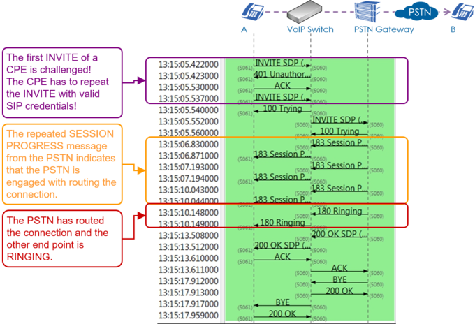
Example of a regular incoming call from the PSTN:
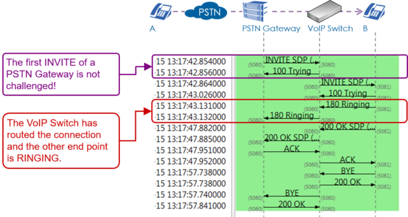
Example of an outgoing call into the PSTN with three exceptional signaling situations:
- The PSTN Gateway 1 doesn't respond so the VoIP Switch has to re-route to the PSTN Gateway 2
- The telephone on side A offers an invalid "Session Time" value which is refused by the PSTN Gateway 2. The telephone on side A has to do a reINVITE with an acceptable "Session Time" value.
- End point B is busy.
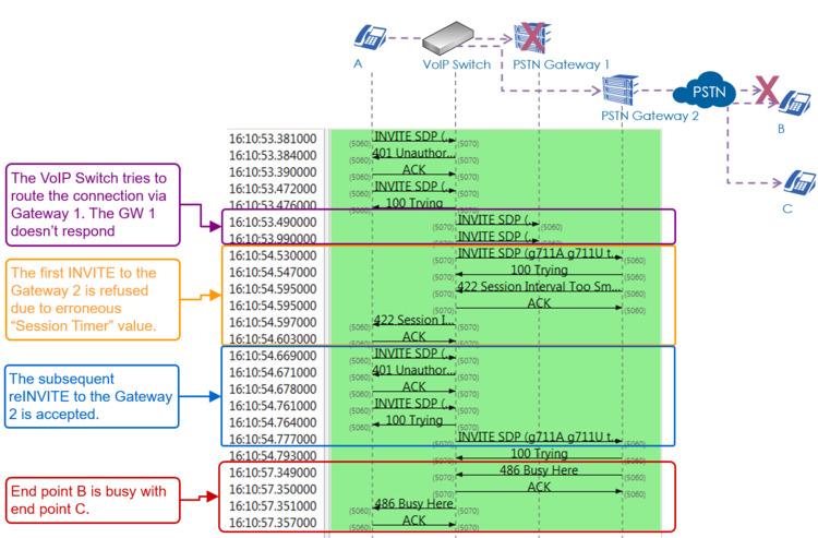
Example of a connection where the VoIP Switch checks the presence of the end points with OPTION messages. The VoIP Switch would release the connection if one end point doesn't respond with "200 OK":
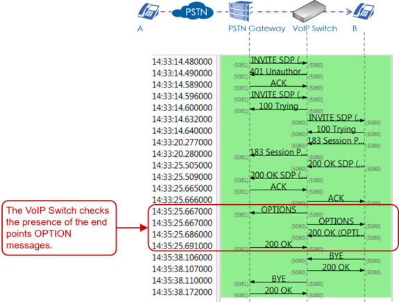
SIP Response Codes
A list of SIP response codes and their meaning can be found here:
Most Important 1xx—Provisional Responses
100 Trying
Extended search being performed may take a significant time so a forking proxy must send a 100 Trying response.
180 Ringing
Destination user agent received INVITE, and is alerting user of call.
183 Session in Progress
This response may be used to send extra information for a call which is still being set up.
Most Important 2xx—Successful Responses
200 OK
Indicates the request was successful.
Most Important 3xx—Redirection Responses
302 Moved Temporarily
The client should try at the address in the Contact field. If an Expires field is present, the client may cache the result for that period of time.
Most Important 4xx—Client Failure Responses
400 Bad Request
The request could not be understood due to malformed syntax.
401 Unauthorized
The request requires user authentication. This response is issued by UASs and registrars.
403 Forbidden
The server understood the request, but is refusing to fulfil it.
404 Not Found
The server has definitive information that the user does not exist at the domain specified in the Request-URI. This status is also returned if the domain in the Request-URI does not match any of the domains handled by the recipient of the request.
406 Not Acceptable
The resource identified by the request is only capable of generating response entities that have content characteristics but not acceptable according to the Accept header field sent in the request.
408 Request Timeout
Couldn't find the user in time. The server could not produce a response within a suitable amount of time, for example, if it could not determine the location of the user in time. The client MAY repeat the request without modifications at any later time.
410 Gone
The user existed once, but is not available here any more.
480 Temporarily Unavailable
Callee currently unavailable.
486 Busy Here
Callee is busy.
487 Request Terminated
Request has terminated by bye or cancel.
488 Not Acceptable Here
Some aspect of the session description or the Request-URI is not acceptable.
Most Important 5xx—Server Failure Responses
503 Service Unavailable
The server is undergoing maintenance or is temporarily overloaded and so cannot process the request. A "Retry-After" header field may specify when the client may reattempt its request.
Most Important 6xx—Global Failure Responses
603 Decline
The destination does not wish to participate in the call, or cannot do so, and additionally the destination knows there are no alternative destinations (such as a voicemail server) willing to accept the call.
Knowhow Media Stream Signaling with "Session Description Protocol SDP"
The Session Description Protocol SDP describes how during a connection setup the end points negotiate the parameters of this exchange as session announcement, session invitation, and parameter. SDP does not deliver media itself but is used between end points for negotiation of media type, format, and all associated properties for voice, Fax, DTMF, bit transparent data etc..
For an extended overview of the SDP protocol visit Wikipedia.
| Note |
The VoIP Switch doesn't interfere in the SDP negotiation of the end points! There may be exceptions for certain Customer Premises Equipment CPE devices where interoperation problems are known. Check with the VoIP switch administrator which CPE devices are known with SDP manipulations by the VoIP switch. |
Basics: Session Description Protocol SDP
The SDP is embedded in the SIP messages during connection setup or connection renegotiation:

The following SDP properties and parameters are important for supporting customer problems:
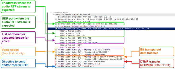
Example of a SDP offer from the calling side A:
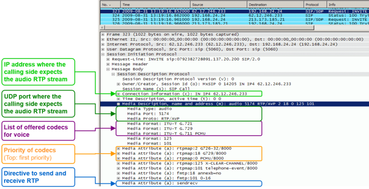
Example of a SDP offer for a Fax transfer with T.38 from the calling side A:
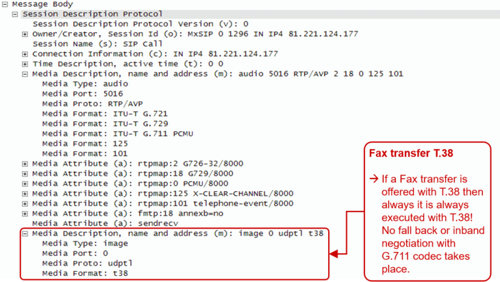
Interpretation of the "Media Attributes":
| Index | Type | Attribute | Remark |
| 0 | PCMU | ISDN G.711µlaw | Very good quality VoIP codec |
| 8 | PCMA | ISDN G.711alaw | Very good quality VoIP codec |
| 2 | G.726-32 | Good quality VoIP codec | |
| 18 | G.729 | Low quality VoIP codec | |
| 125 | x-clear-channel | data service bit transparent | Echo canceling will be switched off and the data bit by bit transferred |
| 101 | telephone-event | DTMF, RFC 2833 | DTMF will not be transferred inband but as RTP event according RFC 2833 |
| 18 | annexb=0 | Special information for codec with index 18 | Special directive for codec G.729 |
| 101 | 0-16 | Special information for for telephone-event with index 101 | 0-15 : DTMF character 0-9, *,#, A,B,C,D 0-16 : DTMF character 0-9, *,#, A,B,C,D, Flash |
Basics: RTP/RTCP
The Real Time Protocol RTP is used to transfer media data, e.g. speech in VoIP based telephony.
The Real Time Control Protocol RTPC transfers periodically statistical media data between the peers of a connection.
If RTP packets are lost, delayed or jitter then we speak of a Quality of Service QoS problem. For the support it is of interest to know if the number of transferred packets between the peers of a connection and if the numbers in the receive and send paths are reasonable equal, if packets were lost on call leg etc. With these statistical media information it can be possible to identify a path or transfer direction were QoS problems occure.
| Note |
The media stream must be proxied via the MediaServer of the VoIP Switch in order to compute statistical numbers of a connection. |
The Aarenet VoIP Switch supports RTP/RTCP statistic data collection of a connection. How they can be obtained is described in article "Manual of the Aarenet VoIP Switch Support Tools", chapter "The ConfigCenter Call Data"
Overview of "RTP/RTCP" information collection:
Details of "RTP/RTCP" information collection:
© Aarenet Inc 2018
Version: 3.0
Author: Aarenet
Date: July 2017
